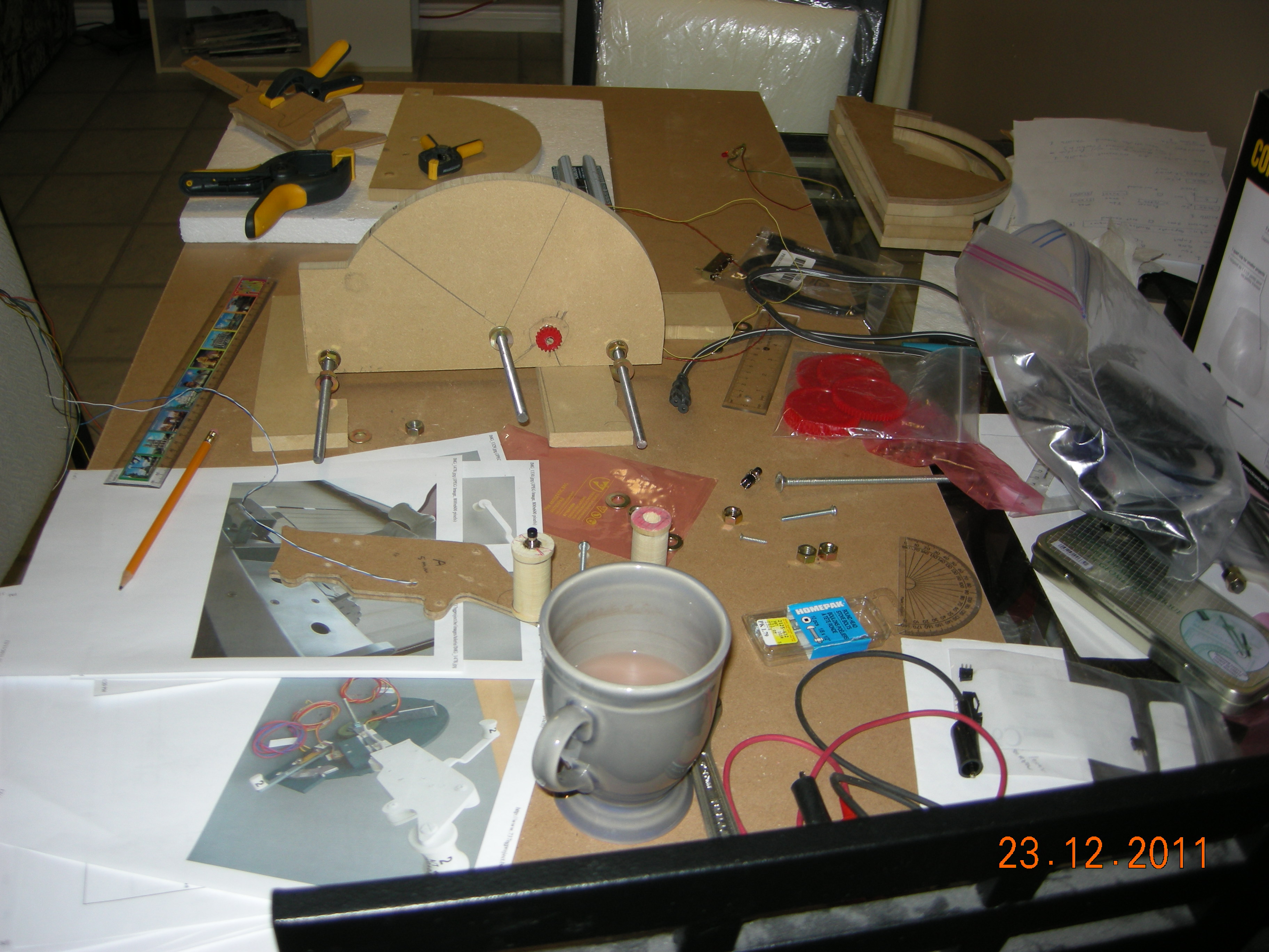
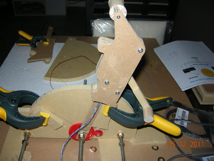
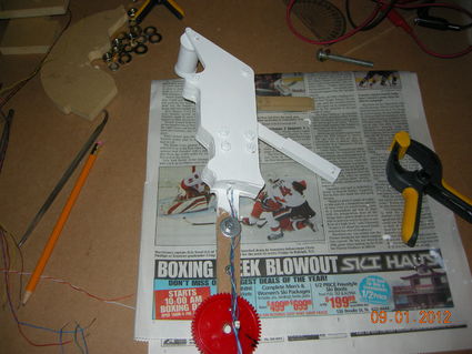
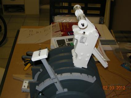
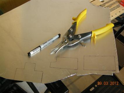
Setting up throttle for
calibration
Centering
throttle
| 
Lining up throttle
stops
|
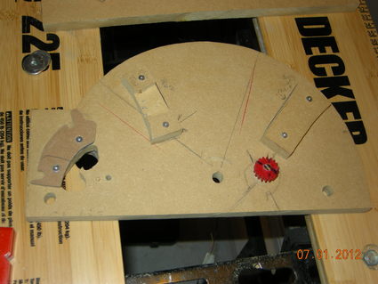
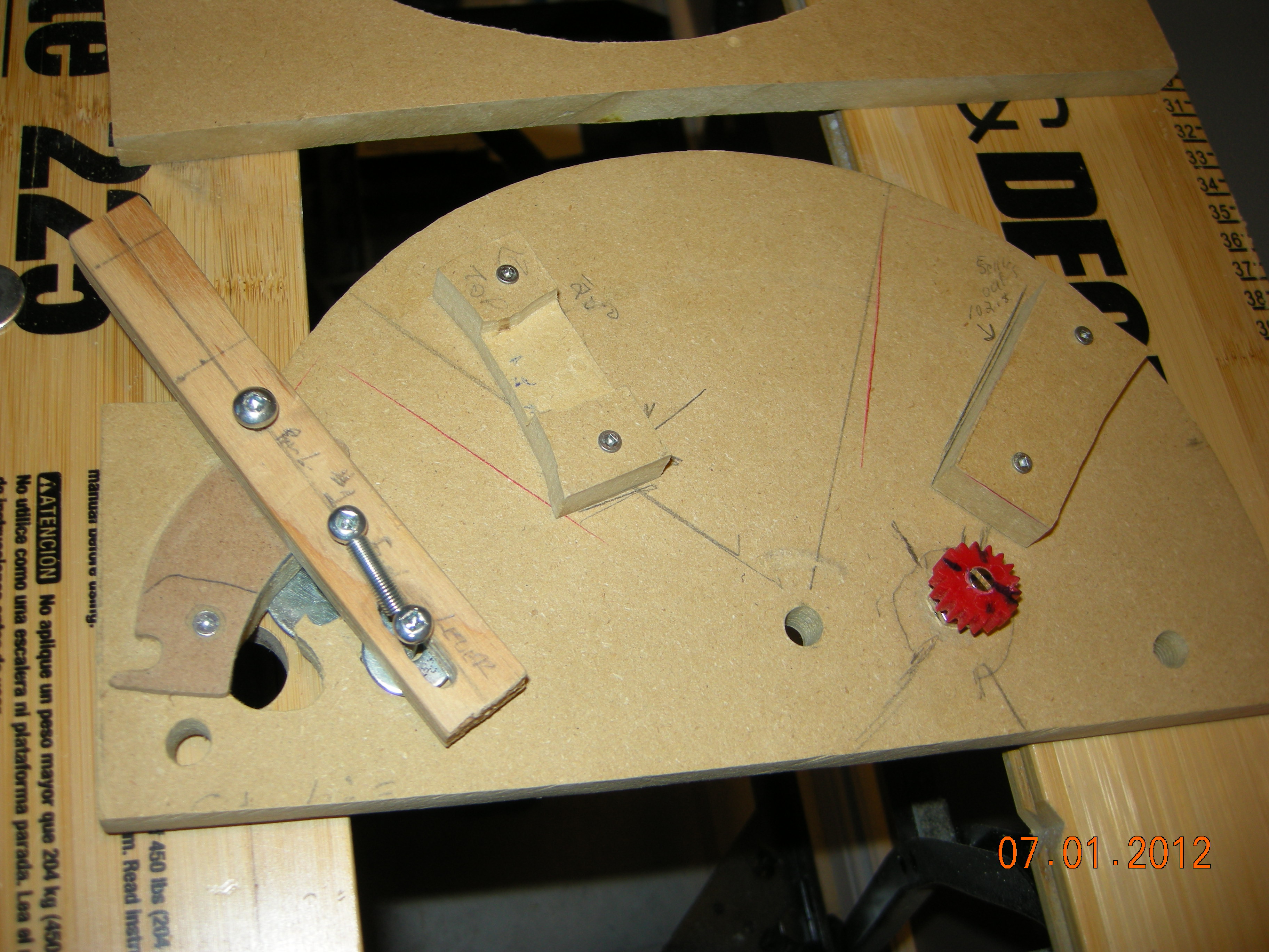
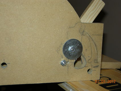
Throttle stops in place.
Min stop routed for idle switch. Fuel cutoff guide in place.
| 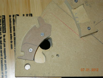
Made the fuel cutoff
slot far too wide but will work.
|

Fuel cutoff lever in ON
position
| 
Fuel Cutoff lever in OFF
position
|
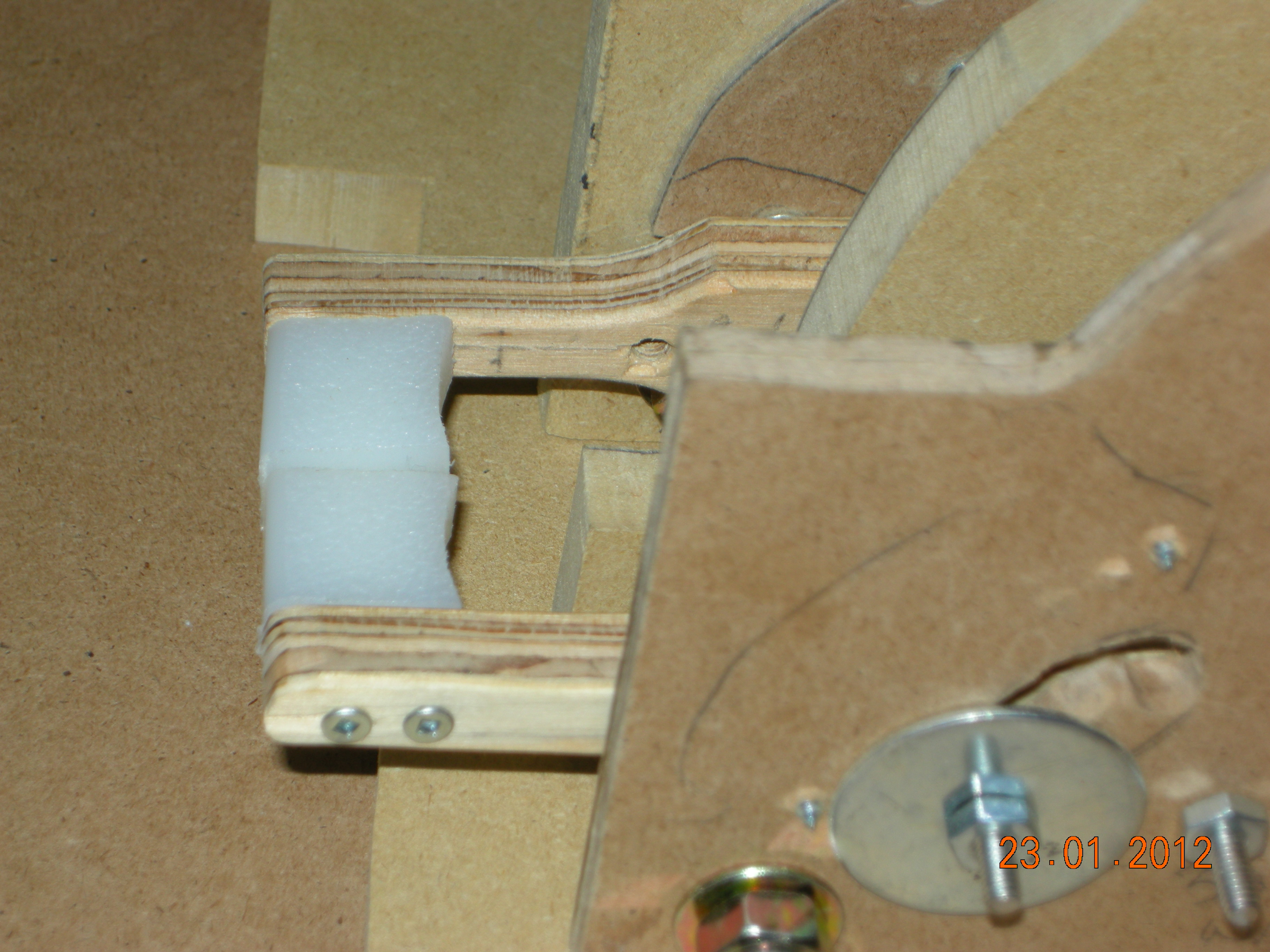
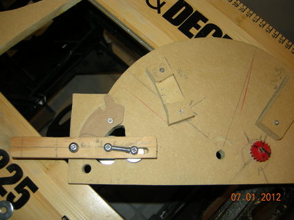
Needed a huge washer
here as I cut the slot too wide. Engine 2 will be smaller.
|
It took many tries to
get this guide right.The idea for the guide design comes from Rudy's site.
|

Throttle Idle switch in
place
| 
The fuel cut off lever
still needs some rework as it is in rough stage
|
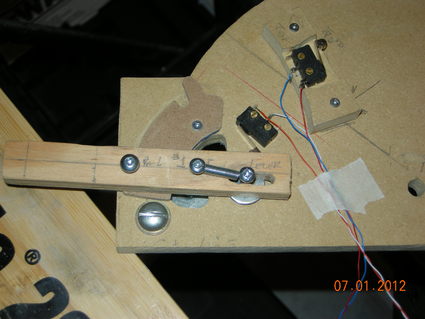
fuel cutoff switch
installed
| 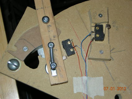
another view of cutoff
switch
|

reworked fuel cutoff levers
| 
knobs made from kitchen cutting board. The left guide screw is out for finishing touches
|
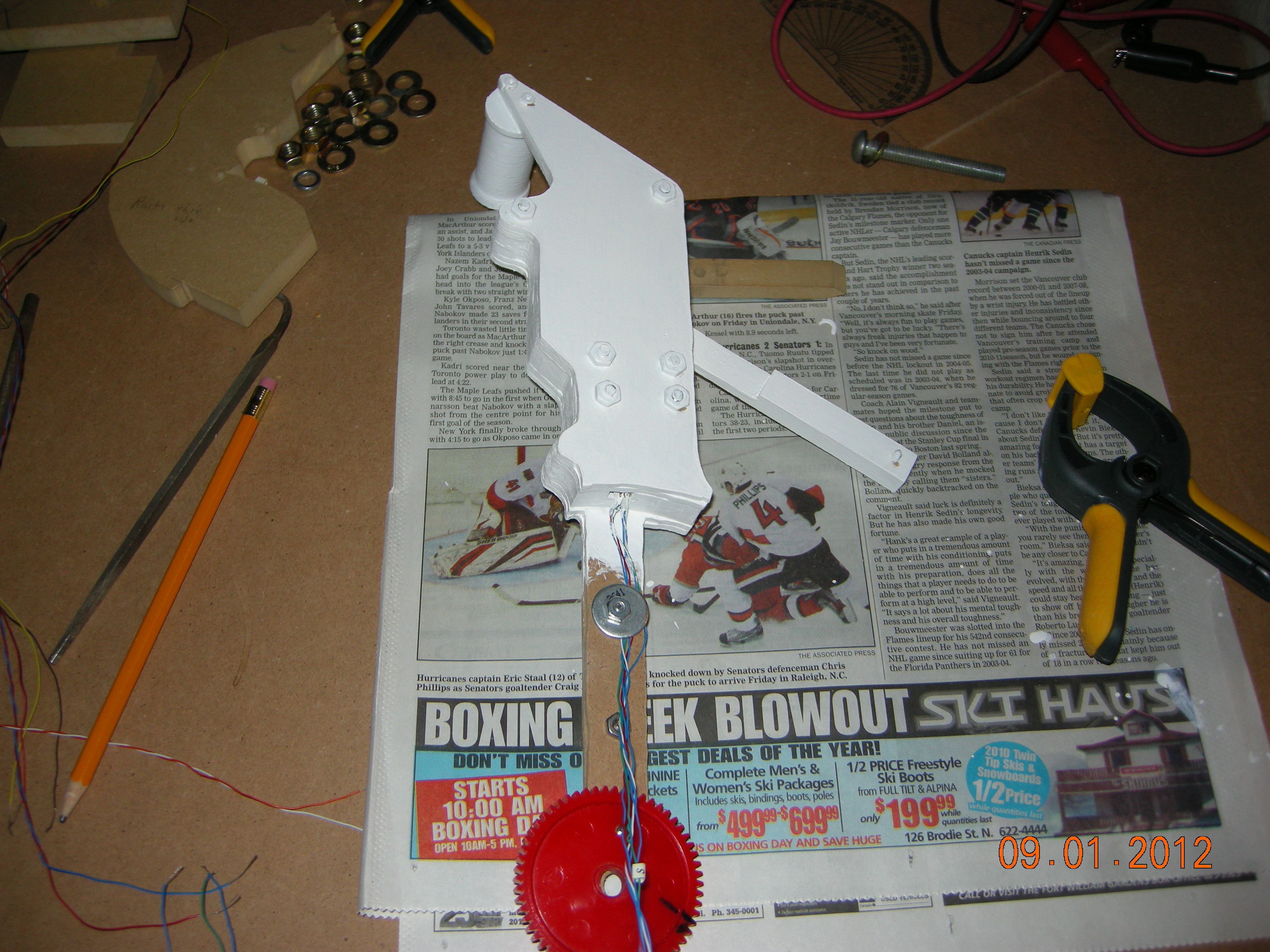
Painting the
throttle. The reversers still need thier respective knobs.
| 
Essentialy the throttle
lever is complete except for the placing of decals
|

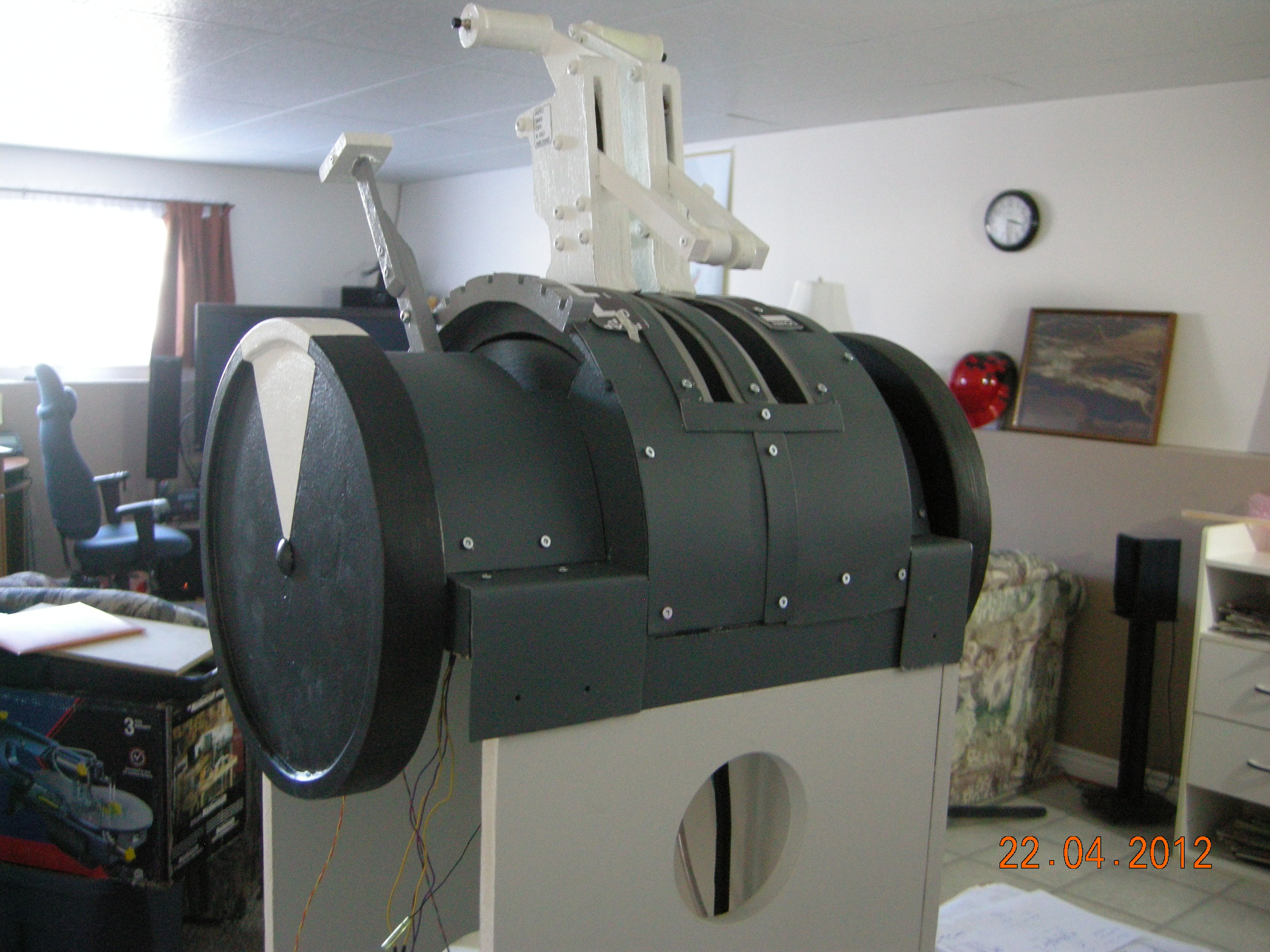
Throttles in place, reversers complete. Paint #2 and add decals. I may beef up the throttle legs as there is is some twist in the mdf
| 
the dust flaps and aluminum covers will finish off the throttle section
|
Beefed up the throttle legs. They are much stronger and run true now, as there was some twist in the mdf which caused lever collision problems when operating one trhottle at a time.
| 
Both throttles painted, only decals left
|
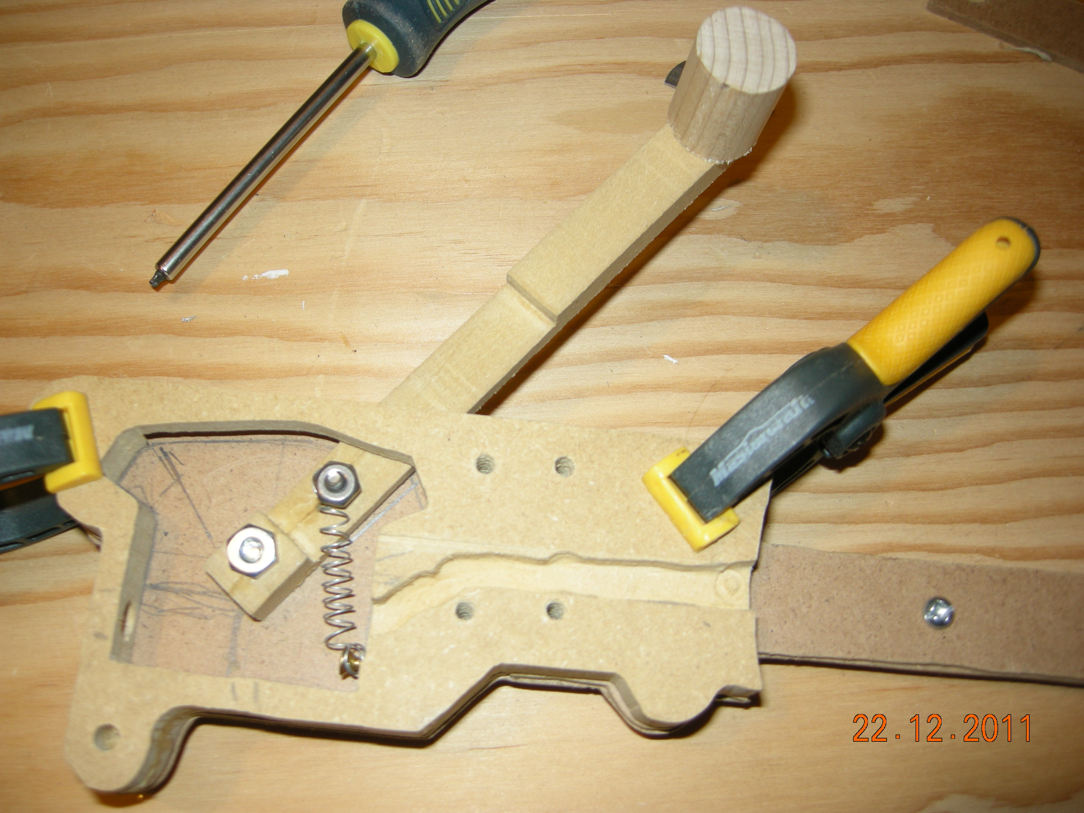
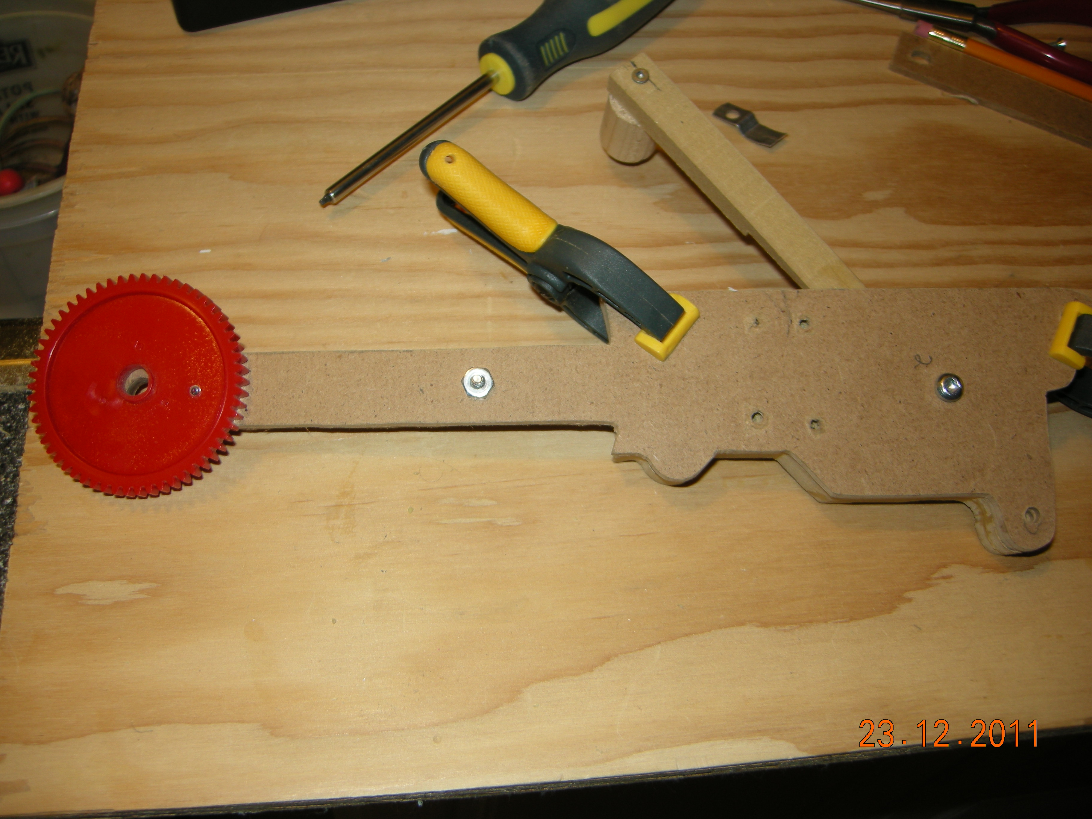
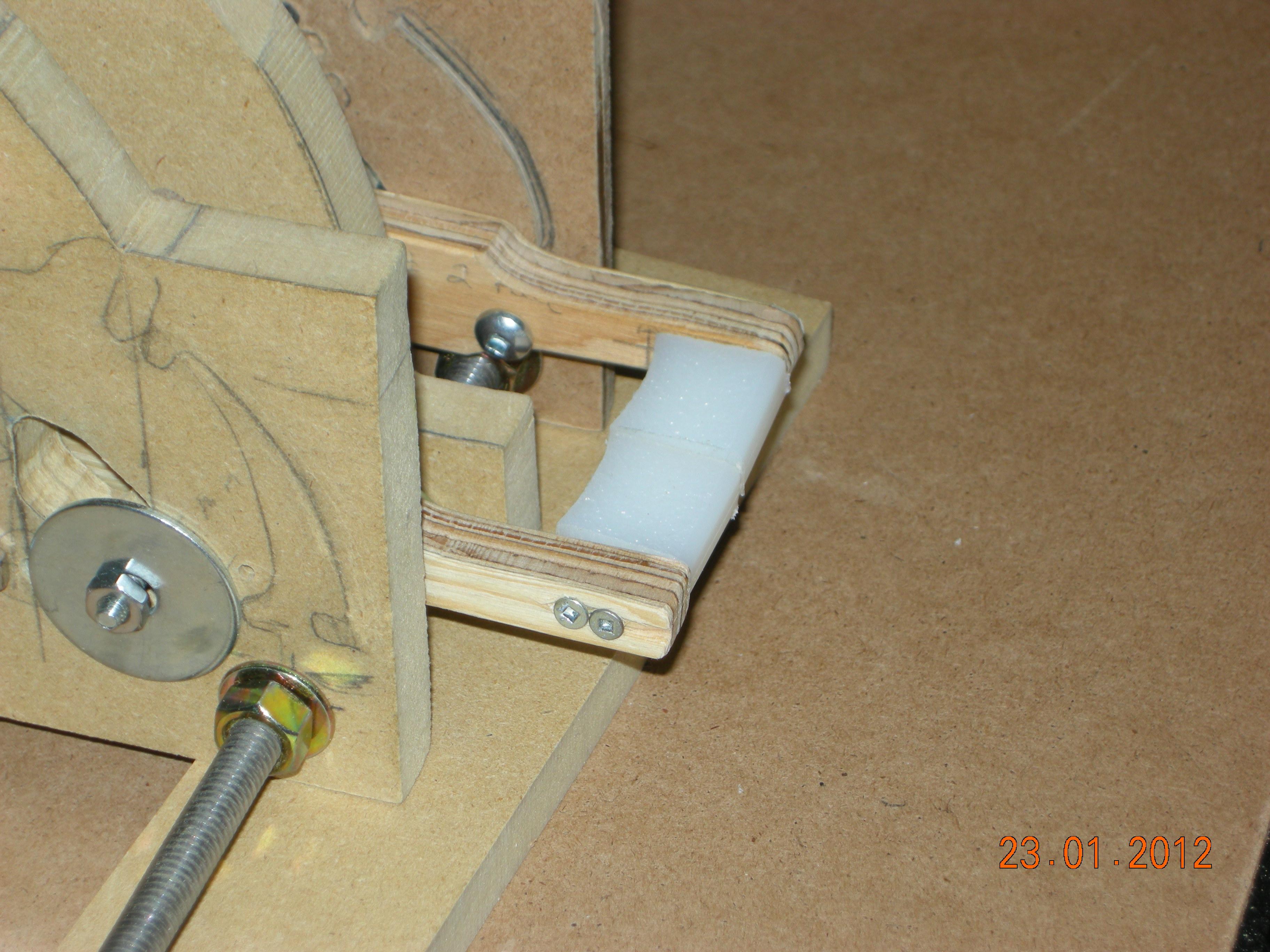
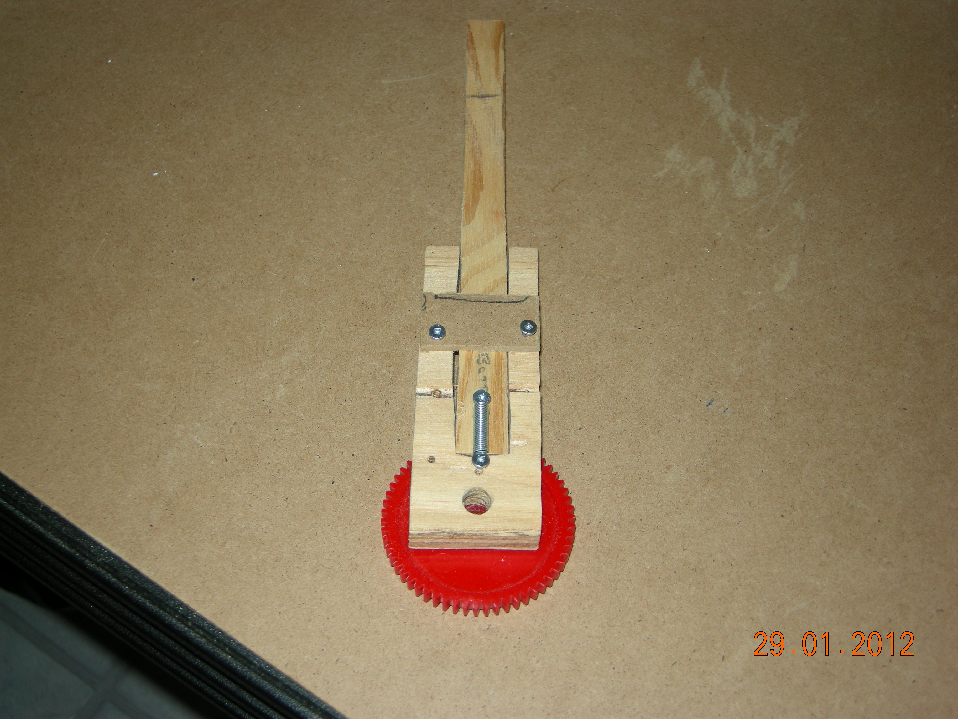
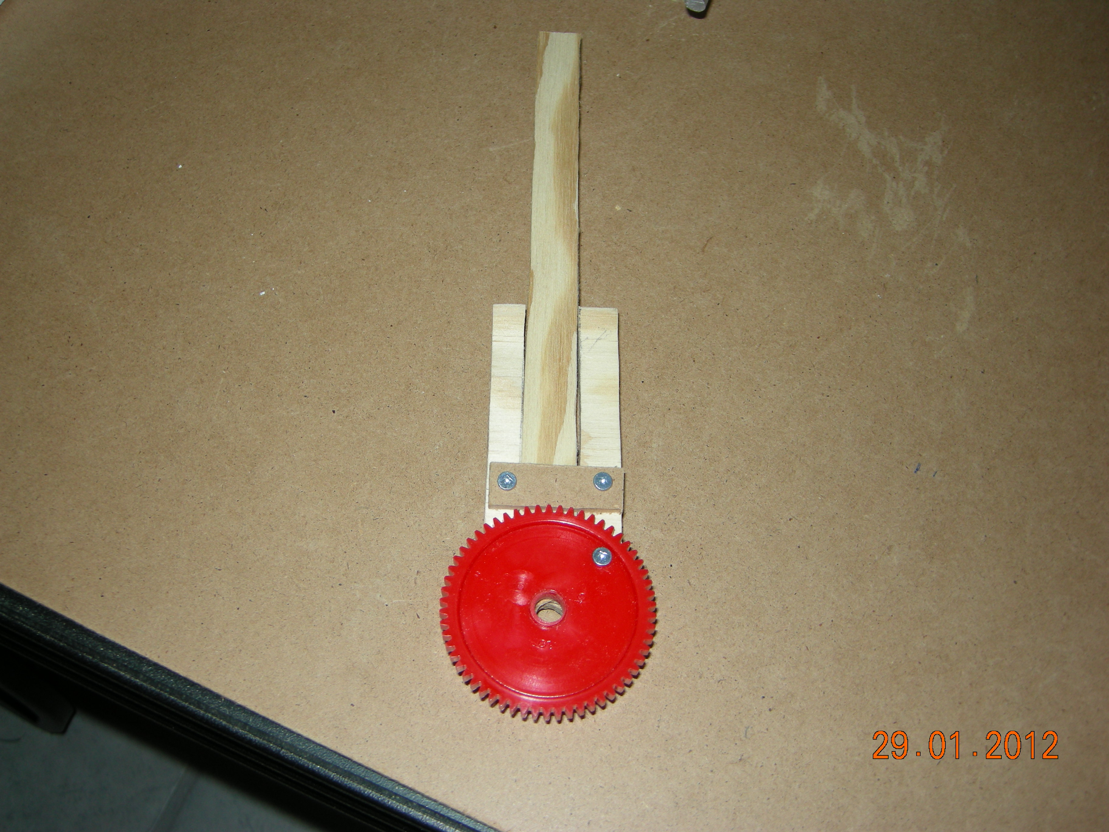
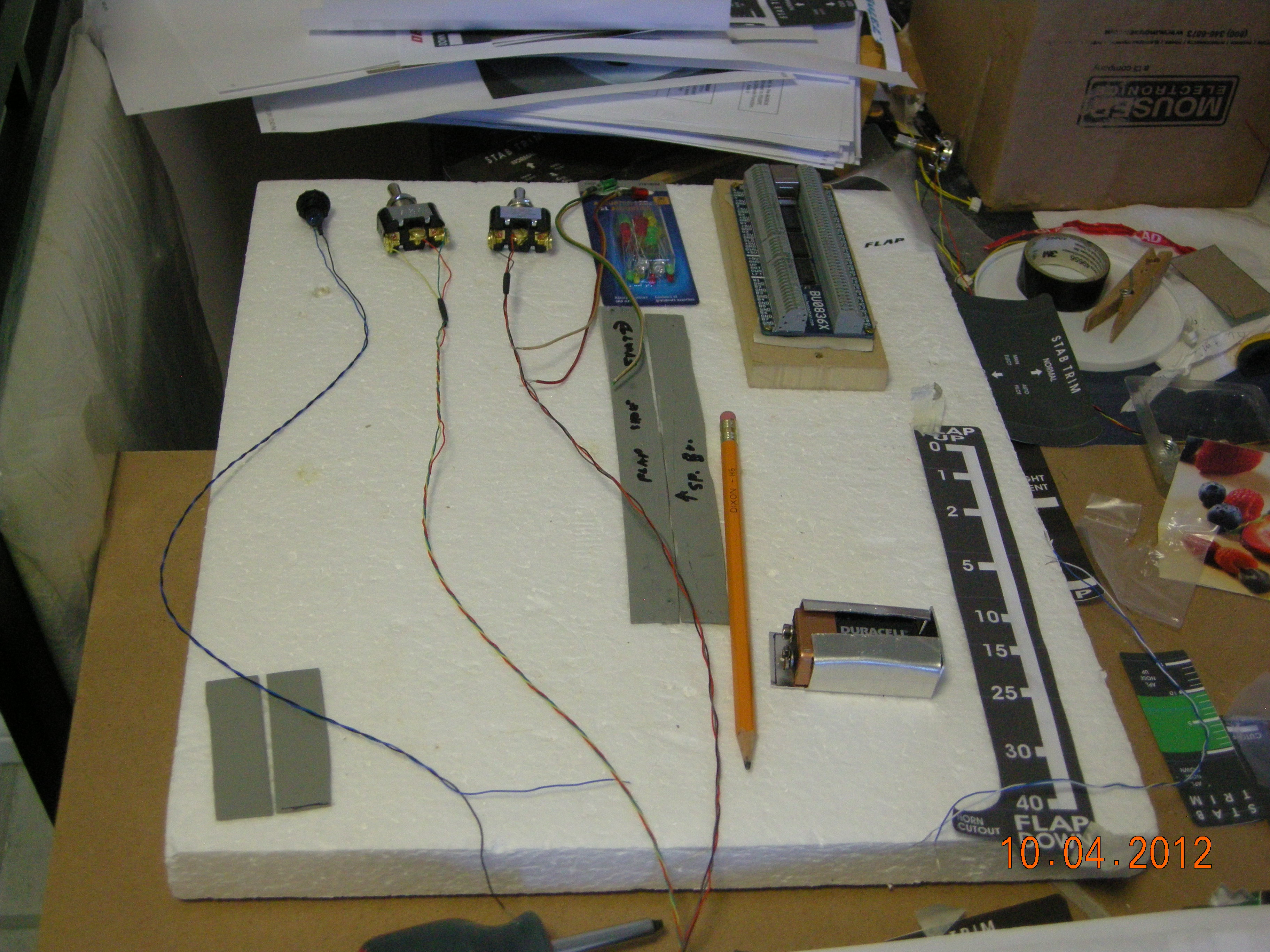
Flap Lever: Cut out of 7/16 plywood, small screws holding spring
| 
Opposite side: Small plates hold lever in place
|
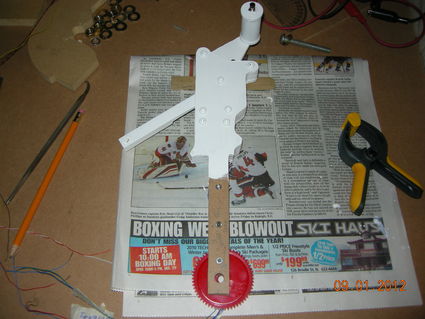
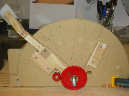
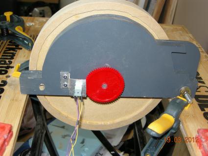
Installing the main gear wheel. I borrow the design for the flap lever from Claus's site.
| 
Rounded the shoulders of the lever retainer and added the top hat, made from kitchen cutting board.
|
Notice the long bolt in the flap lever. I am hoping it will do double duty as marking device for the flap graduation scale.
| 
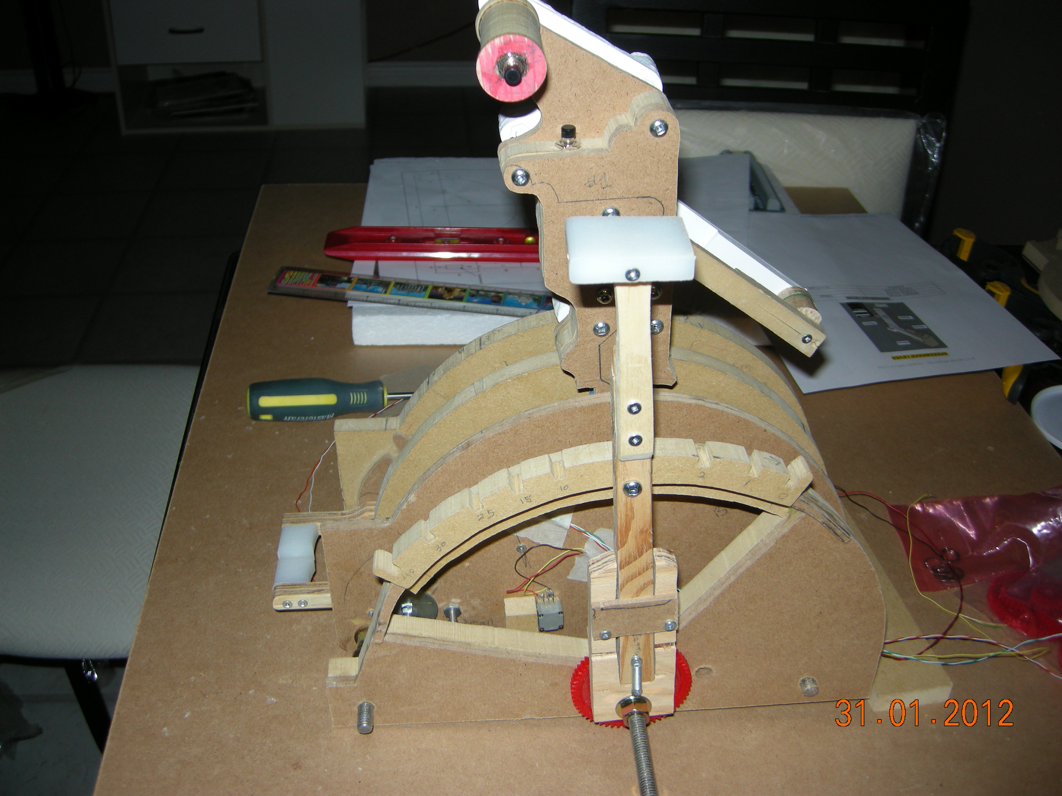
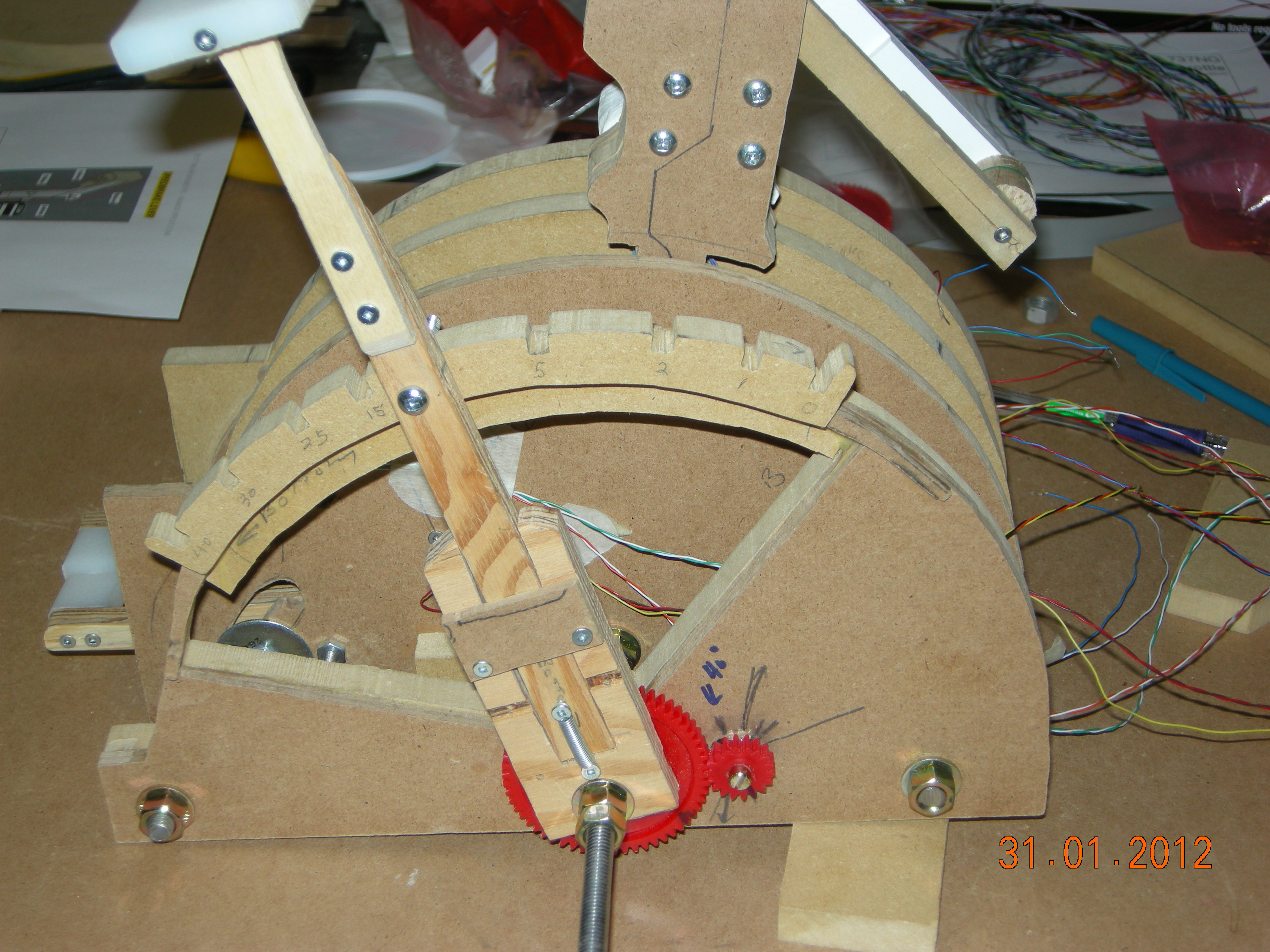
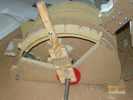
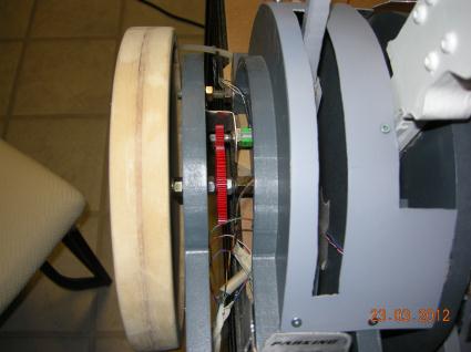
Install the 18 tooth gear and pot.Beefed up beneath the flap detentes'. Calibrated the detentes' in FSUIPC4
|
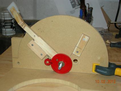
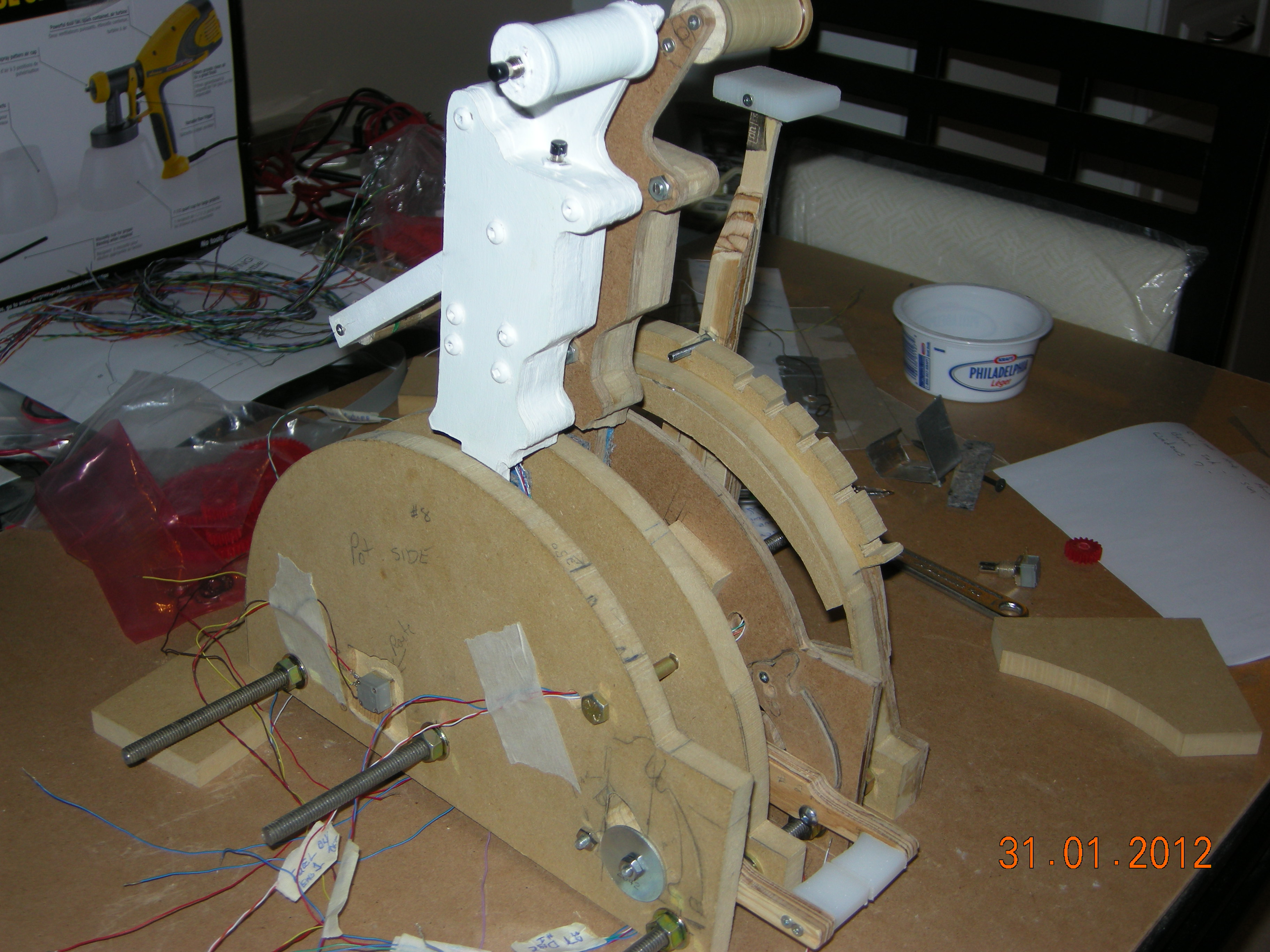
New design. gears aligned and stops in place.Many thanks to Lloyd Bryor for the ball bearings.
| 
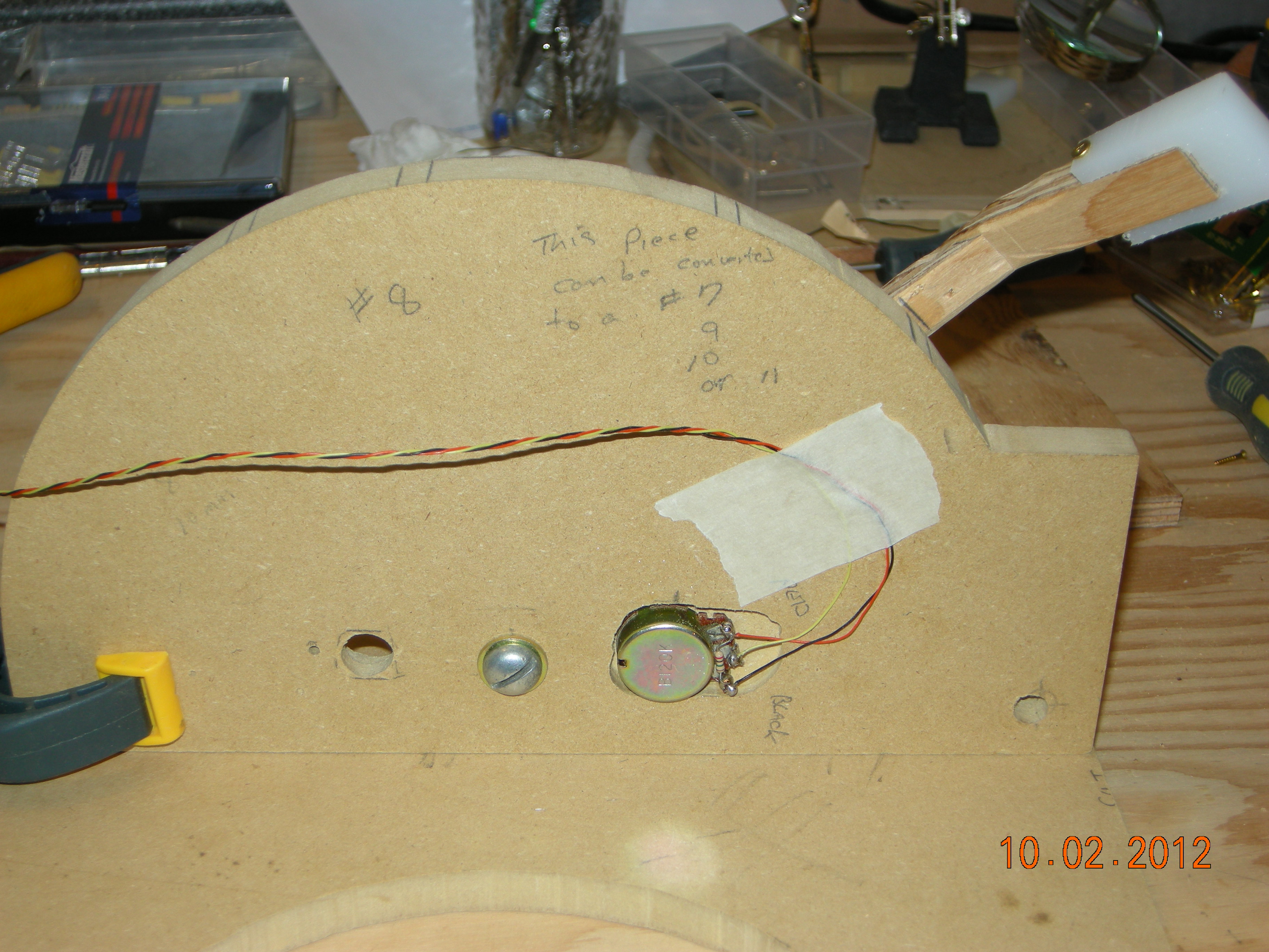
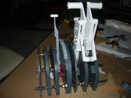
Back side showing pot and new plate
|
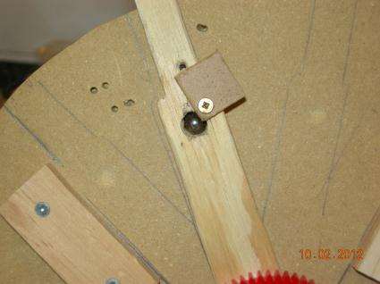
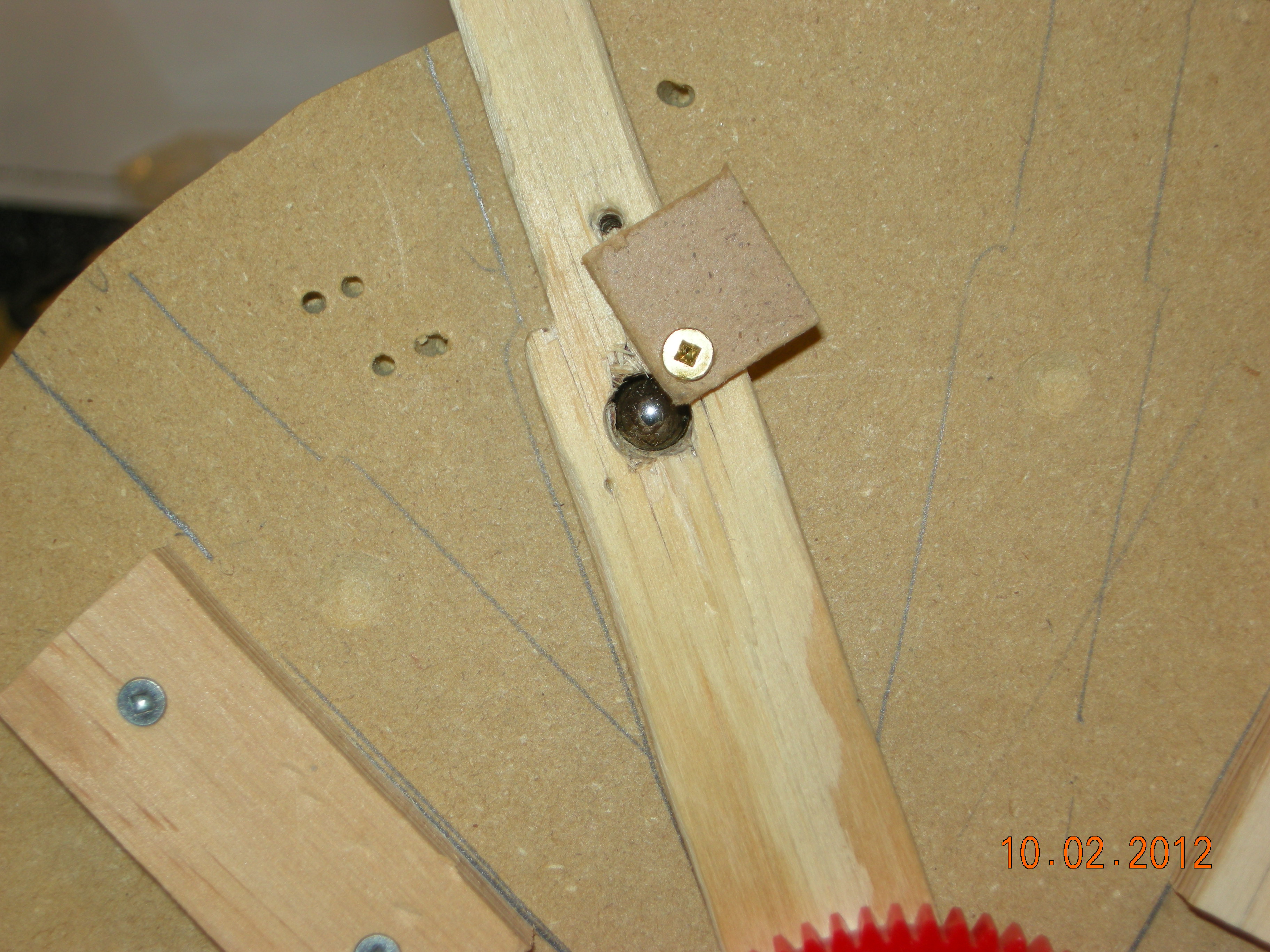
A ball bearing sits in the hole, cover plate attached to hold ball and spring in place.Look closely for detente holes. They must be very small to allow smooth action of the ball.
| 
Notice the spring size. It will fit in behind the ball and cover will hold the two in place.Indents can be seen clearer in this photo.
|
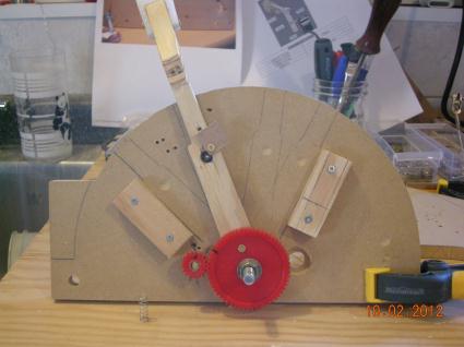
Cover is in place. Next step is to calibrate. Back to the FSUIPC4 Manual now.
|
I'm pretty sure I'll modify a new piece to cover more of the flap lever opening, as I changed the flap lever design somewhat.
| 
Close up of flap lever opening
|
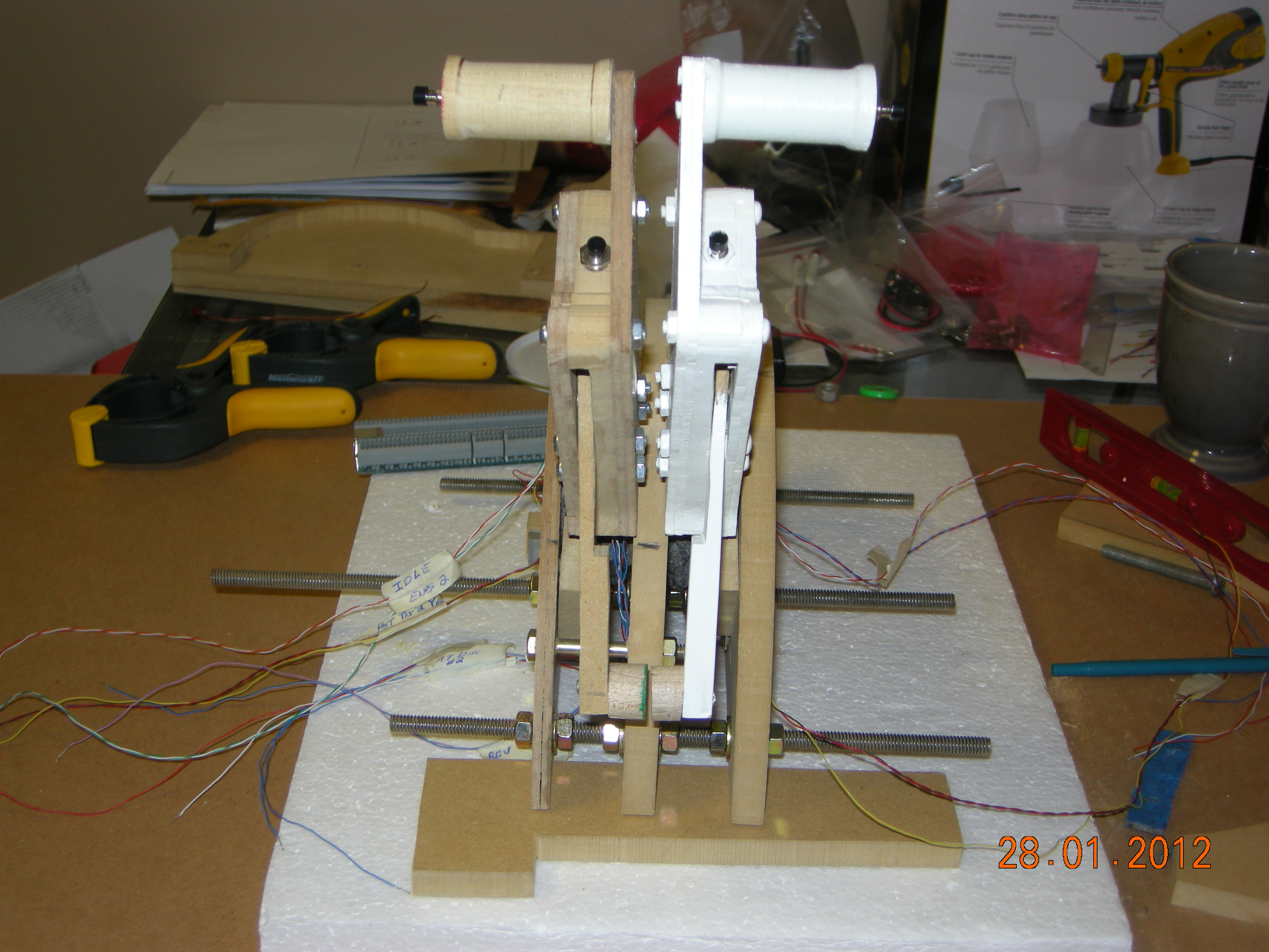
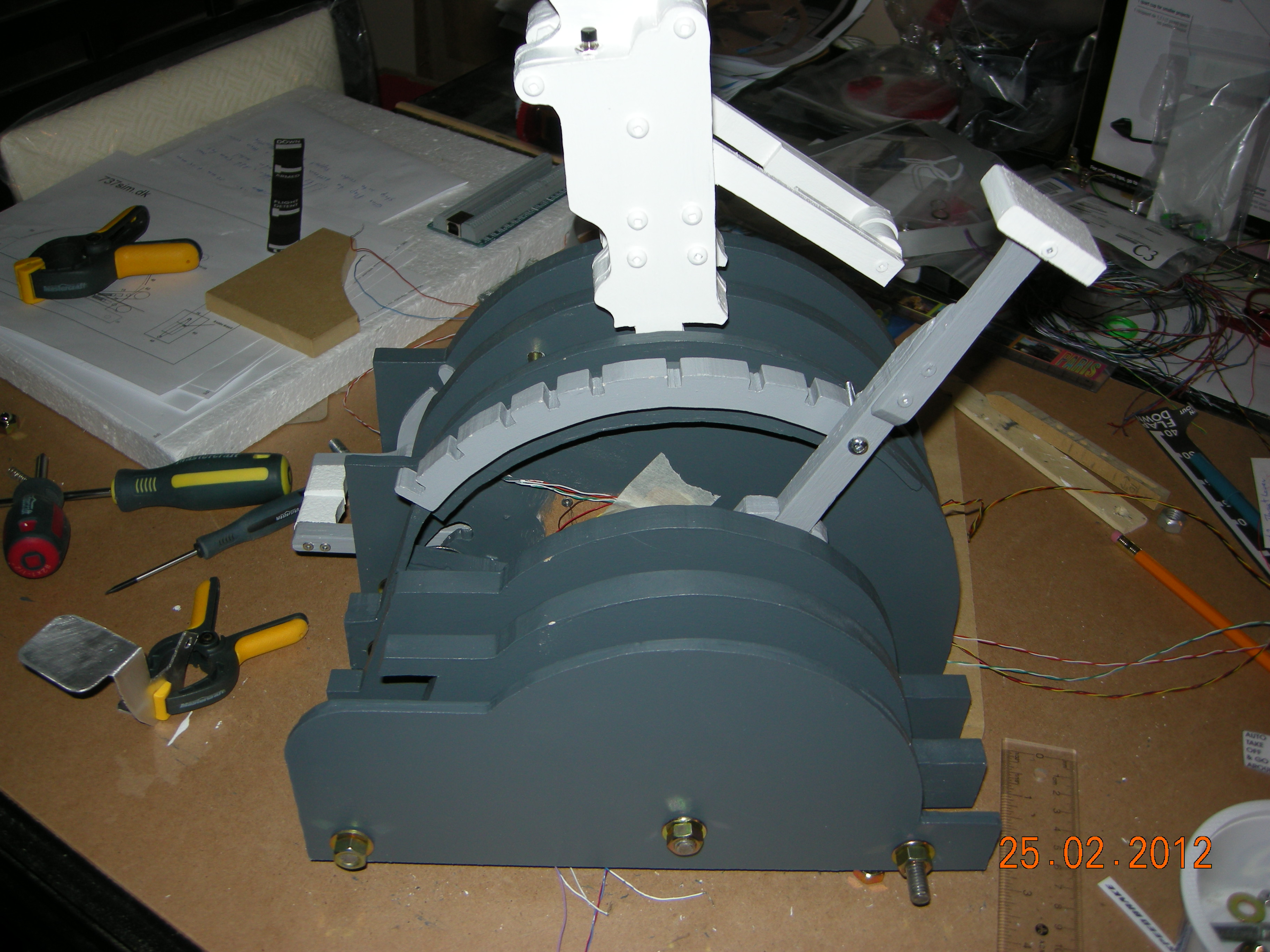
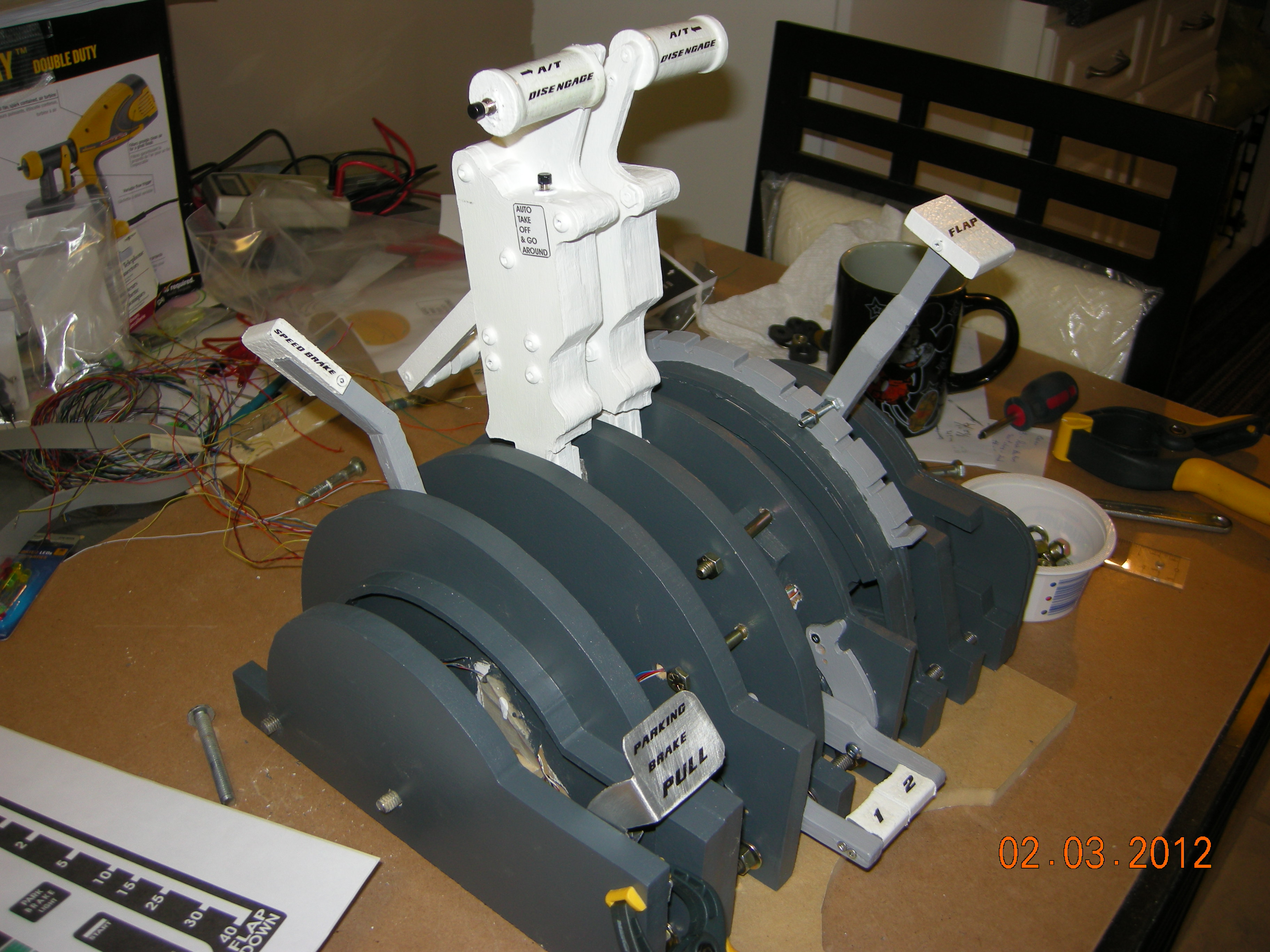
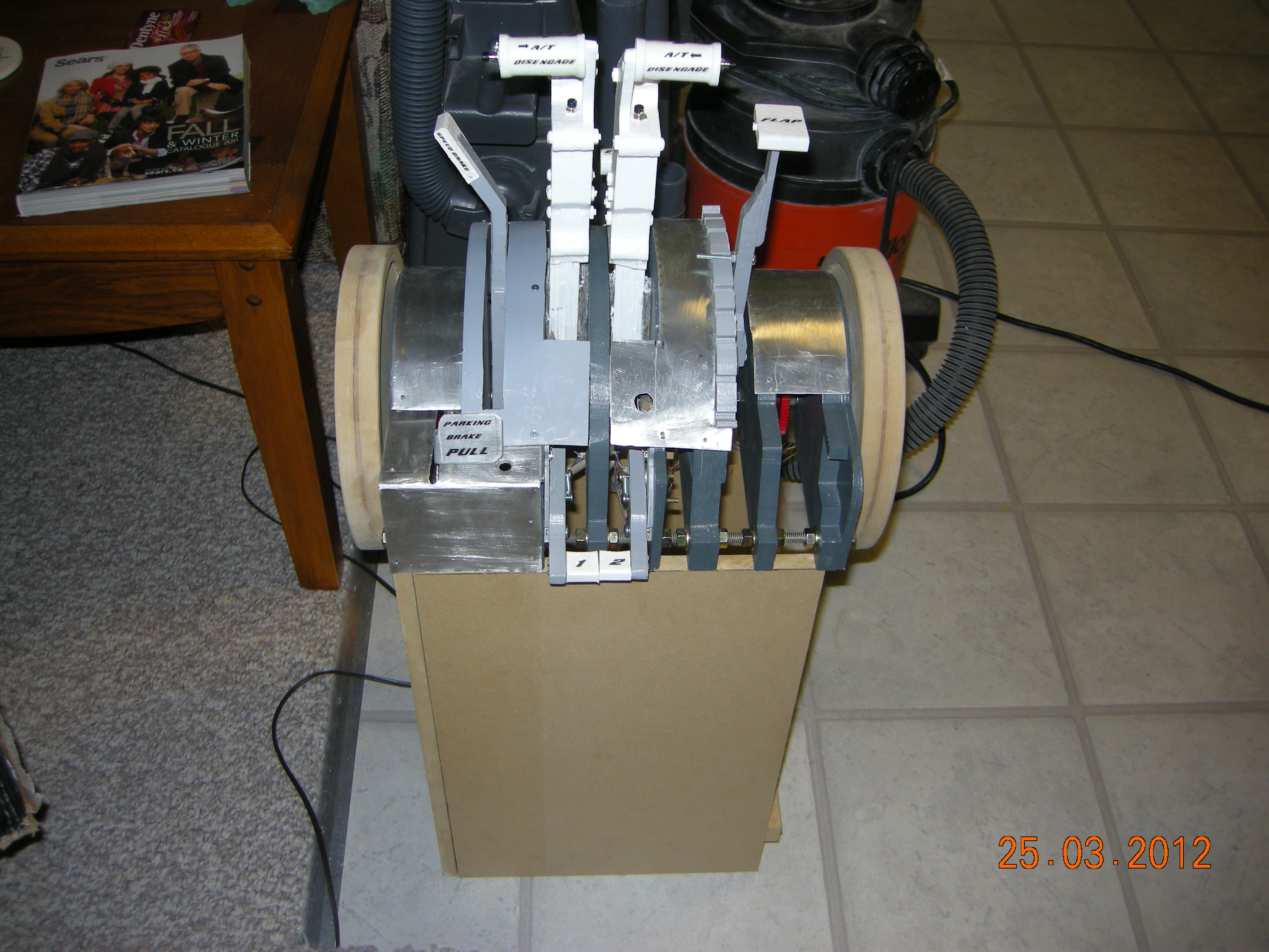
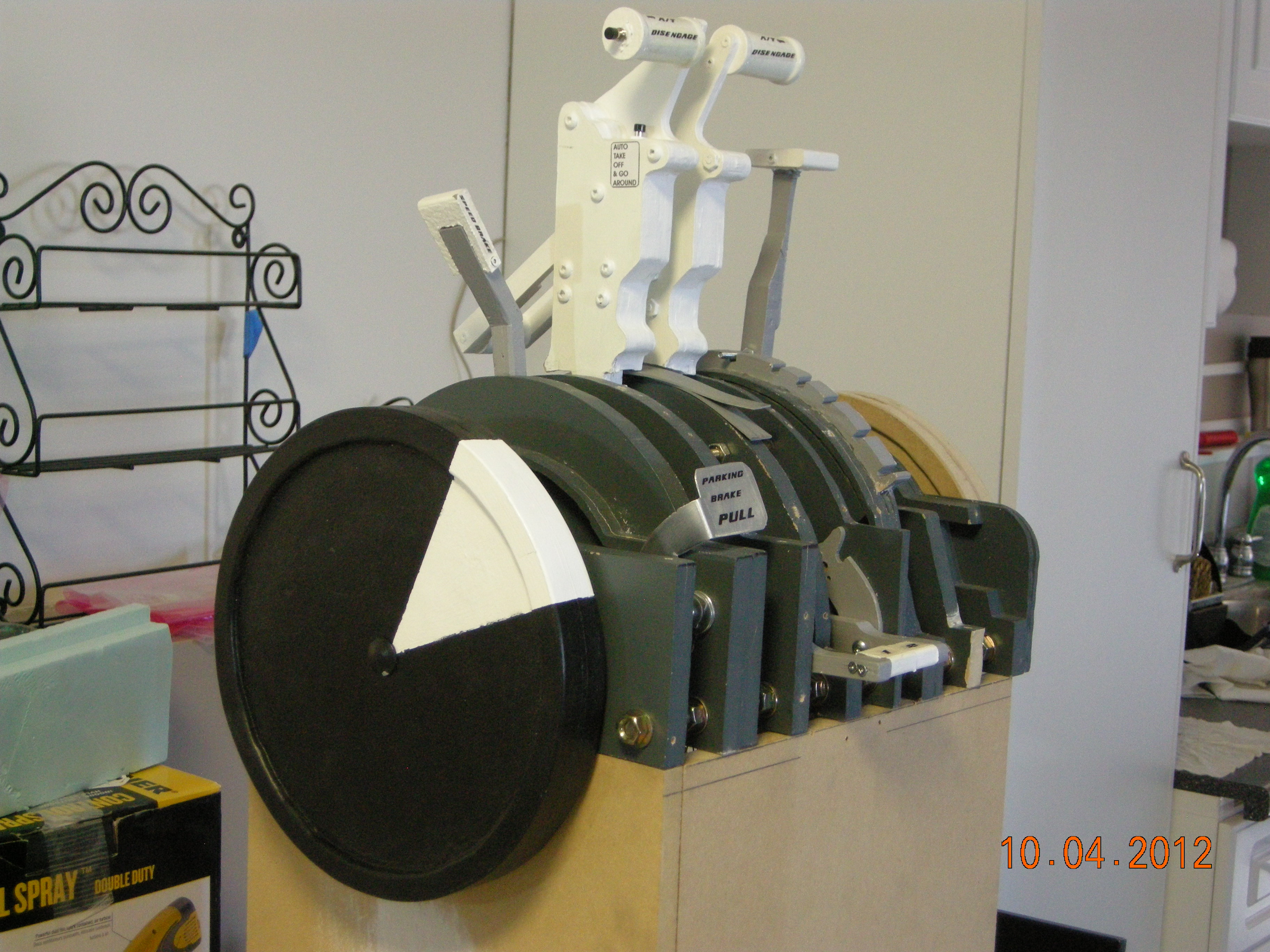
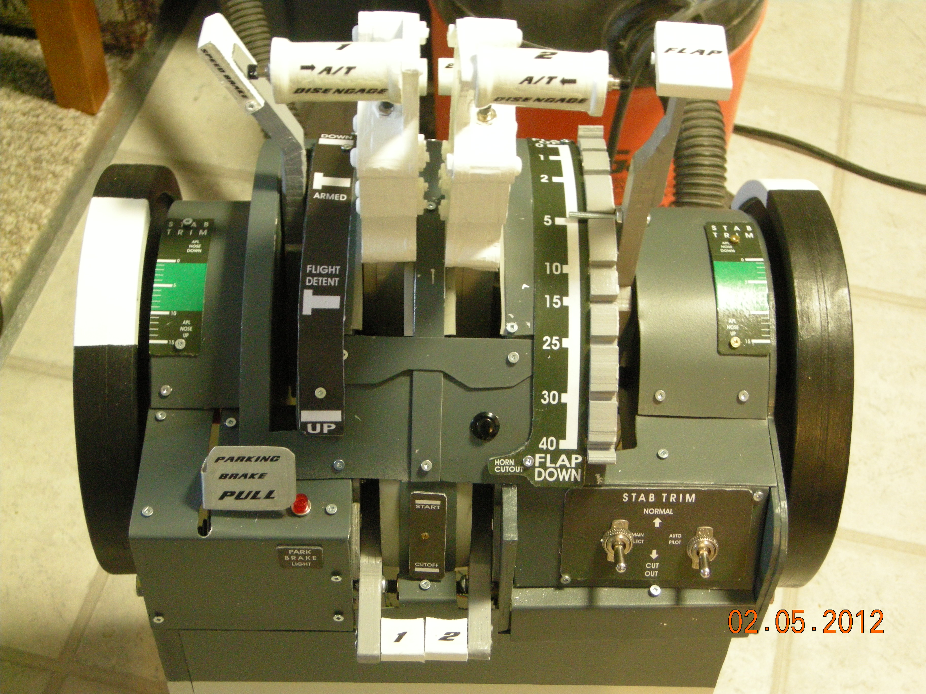
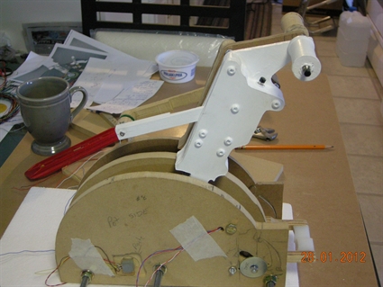
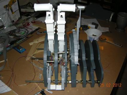
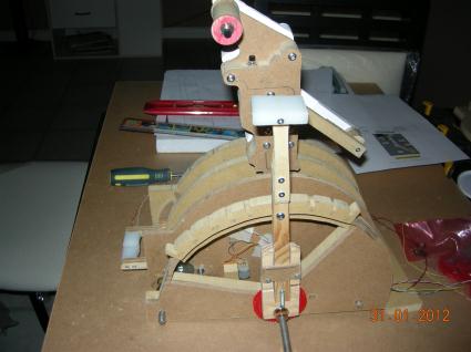
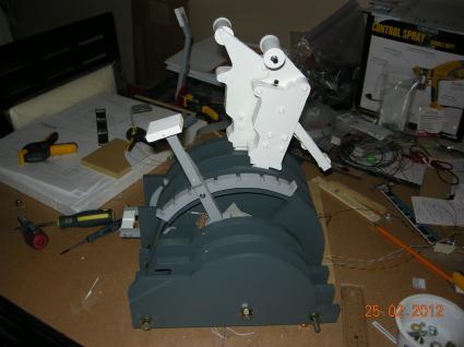
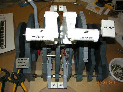
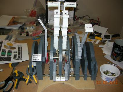
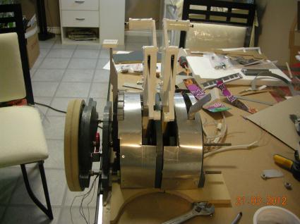
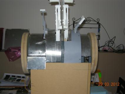
Front view of assembly to date. It starts to look like a throttle.
| 
The parking brake cutout. I borrow the design from Claus's site.
|

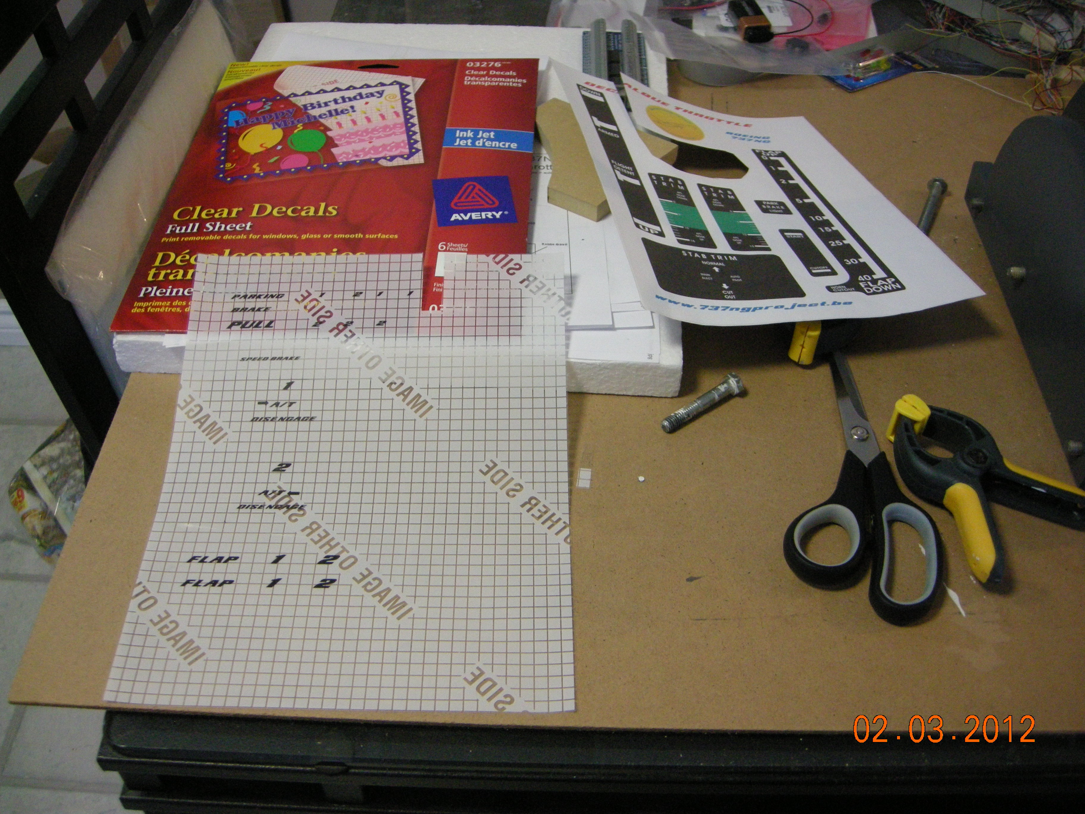
The Avery decal sheets, one set clear transparent, the other white with sticky back
| 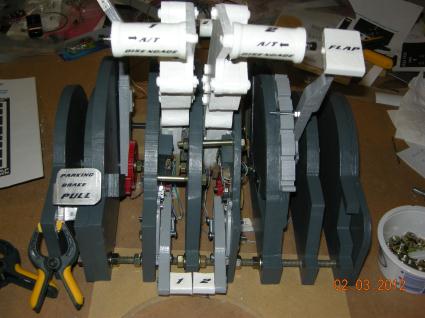
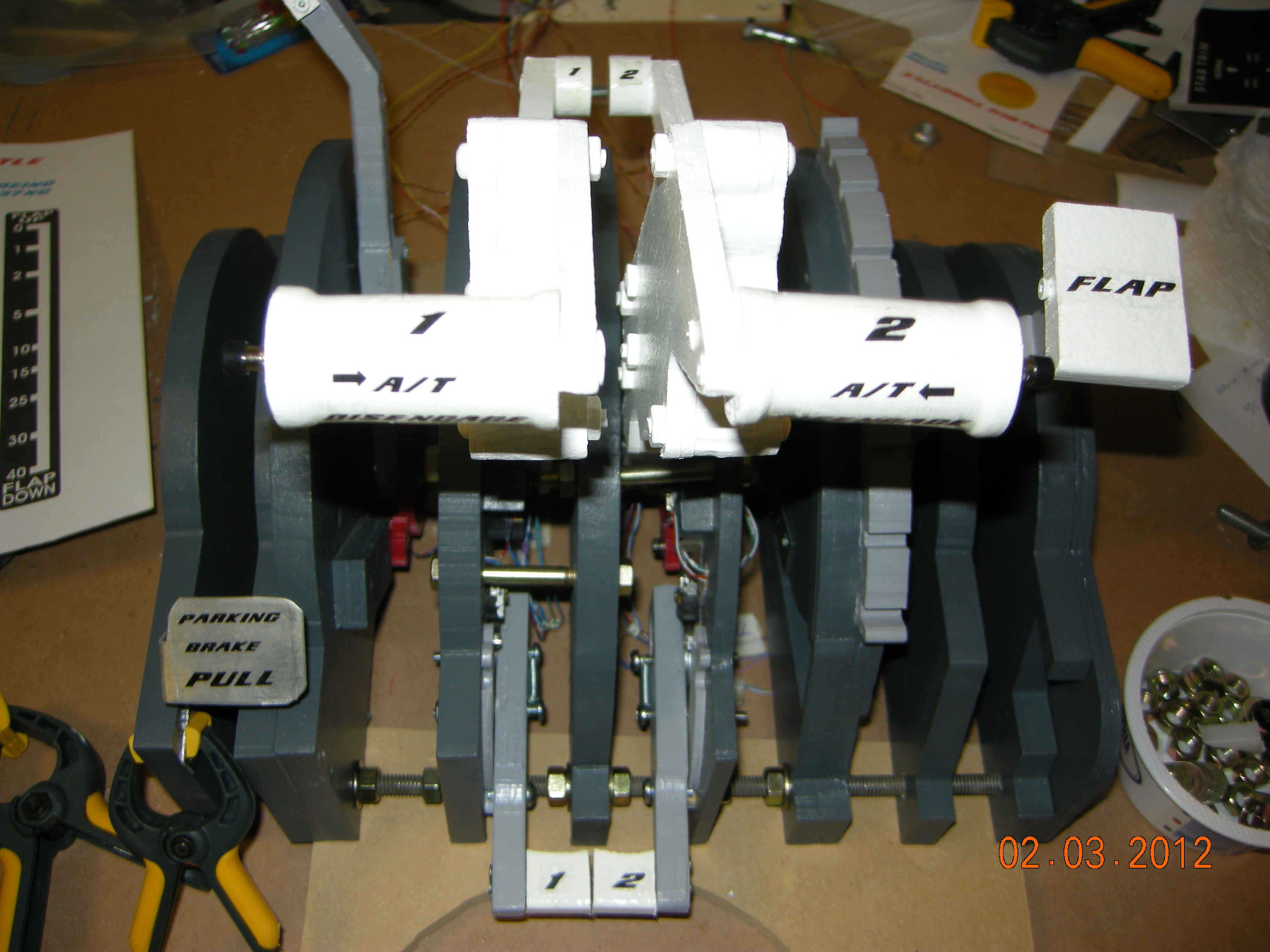
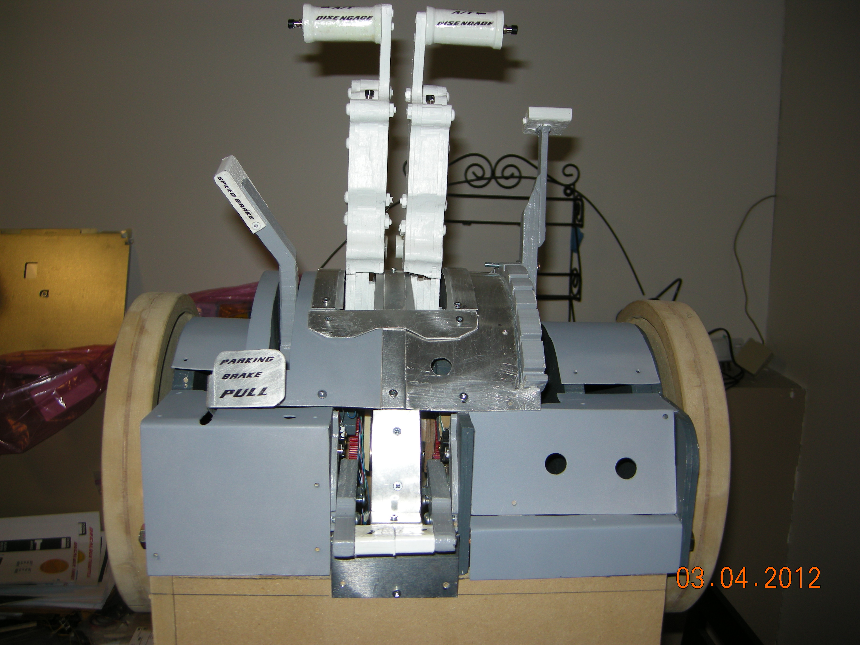
Front view, flash a bit bright
|
View of the thrust reverser numbers
| 
I may clear coat the flap graduations as I notice a bit of paint wear there
|
The TO/GA decal was printed on white Avery sticky paper. I didn't clear coat either of them.
| 
I sanded and then cleaned park brake with acetone before applying the decal and clear coats.
|
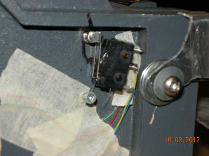
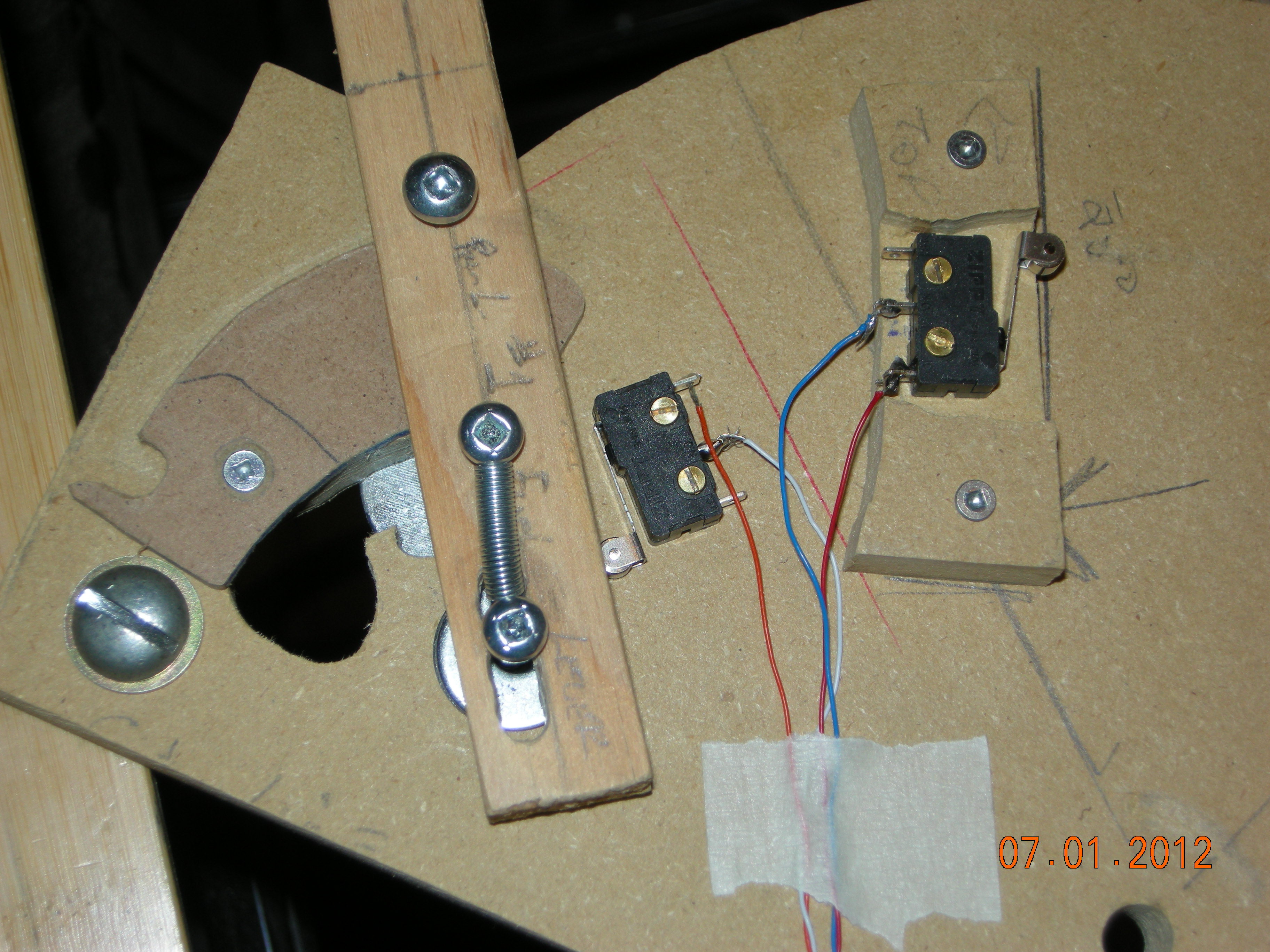
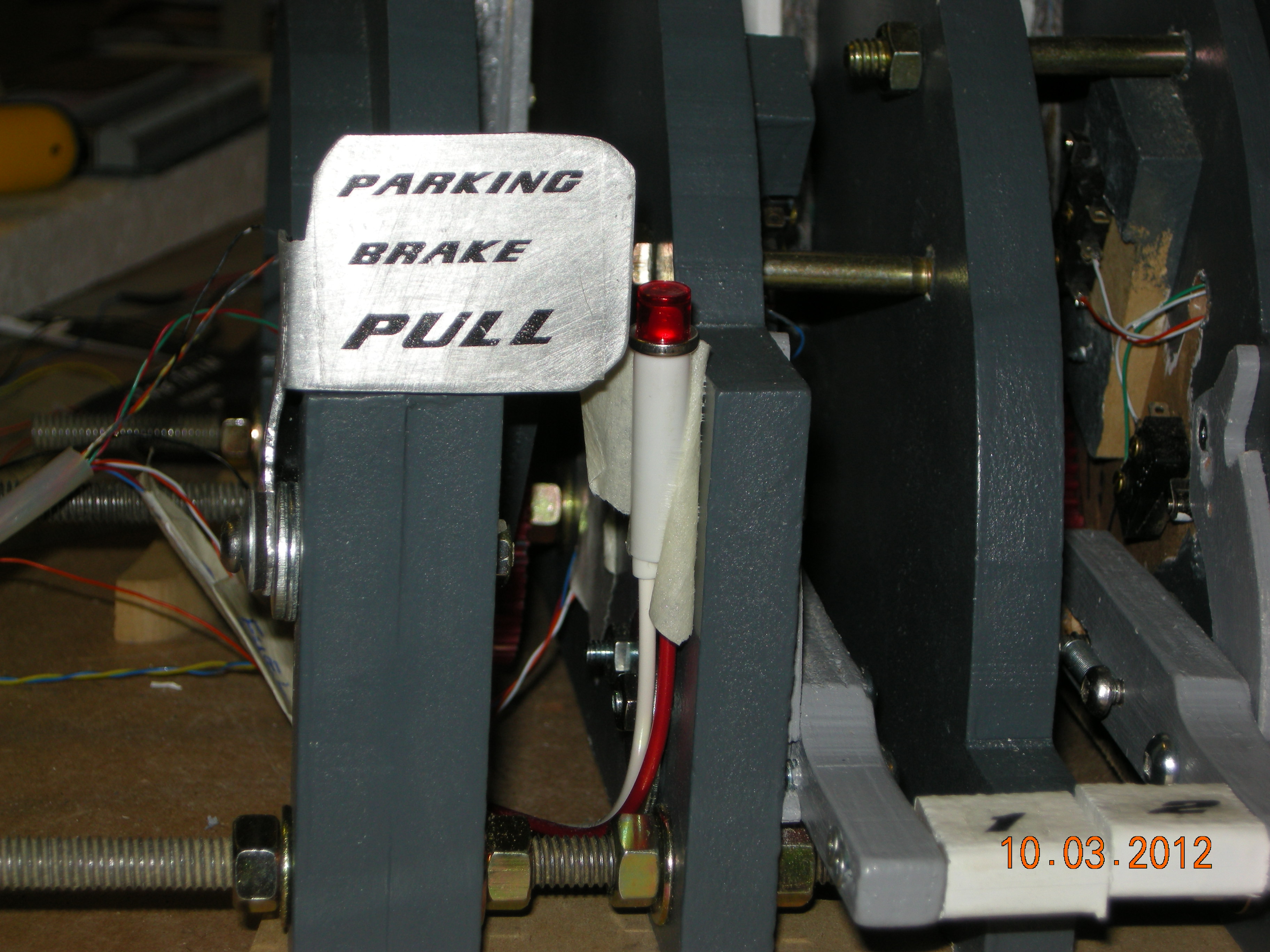
Piggy backed 2 switches. One for brake application, the other activates the LED. Tape between two switch contacts to prevent shorting.
| 
Parking Brake On. Foot pulls back contacts. Screw stops the foot when brake released.
|

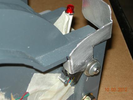
Brake on. Led lit from 5v on Bodnar card. Lever works on friction basis with a rubber washer. Idea from Claus and works very well.
| 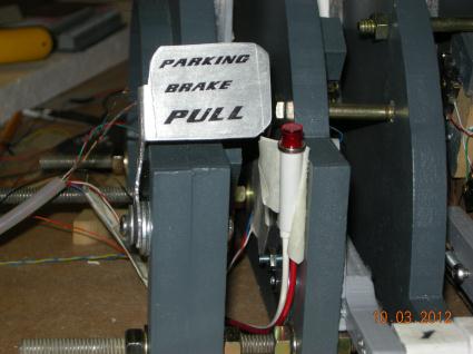
Parking Brake Off position. After finding right friction tension, a dab of glue holds the nut in place. Boeing Font can be found on Rudy's site.
|

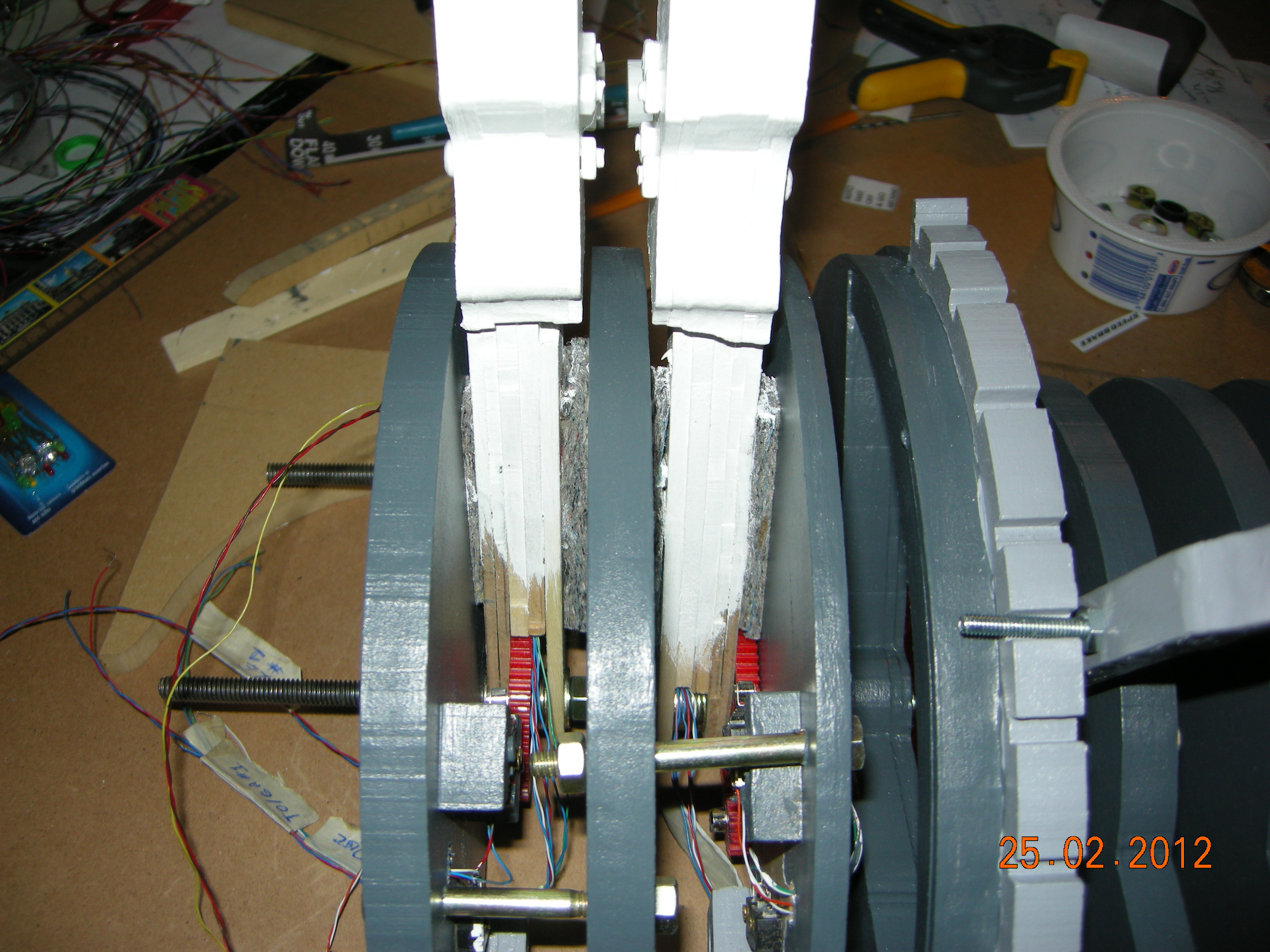
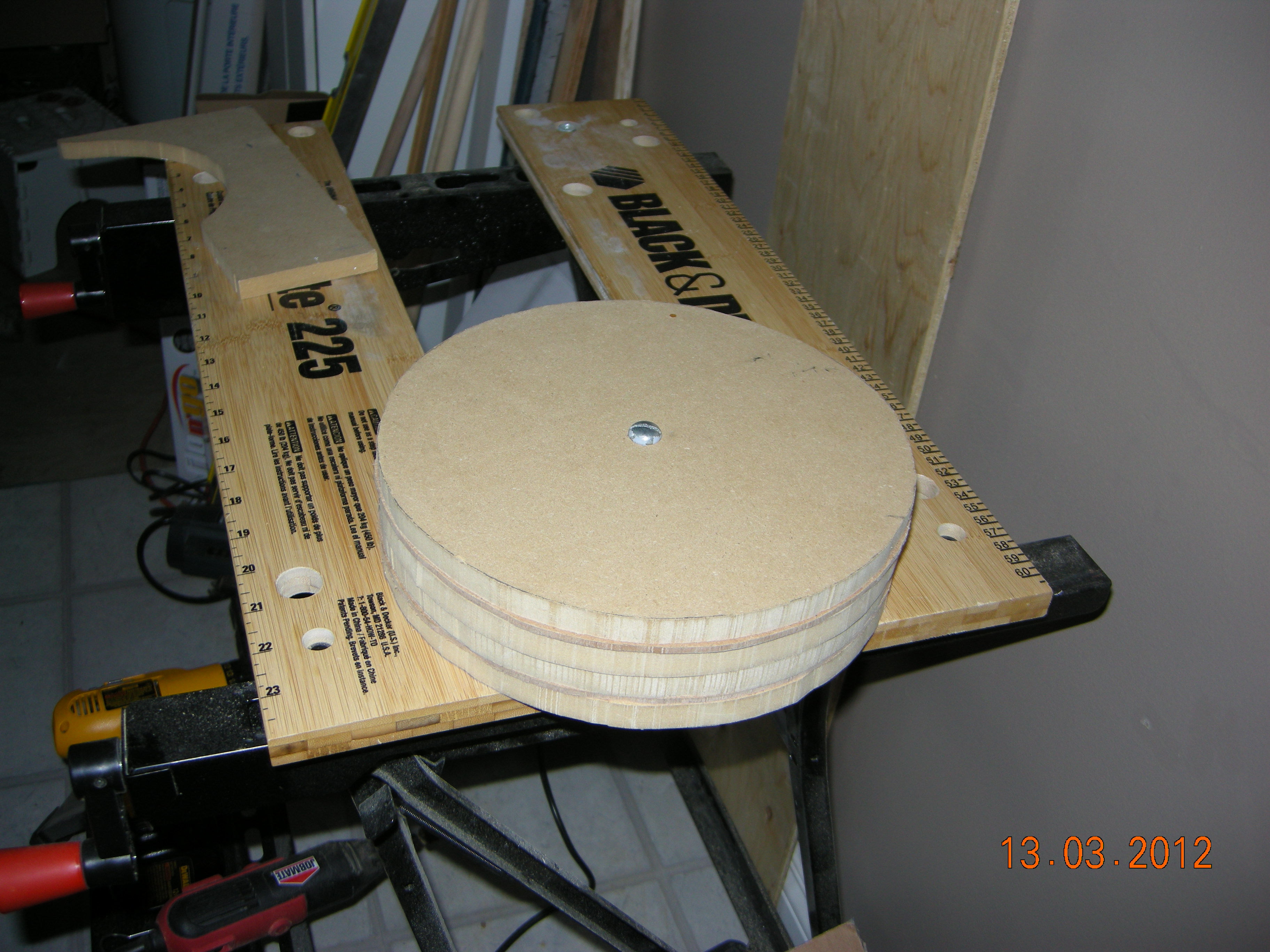
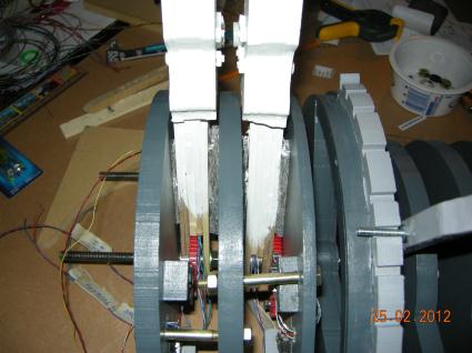
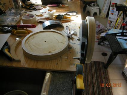
Two trim wheels bolted together for sanding of the outside edges. Radius is 115 and the diameter is 230mm. 2 x 12mm mdf with 4mm hardboard sandwiched between the 12mm pieces. Total thickness with glue 30mm
| 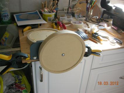
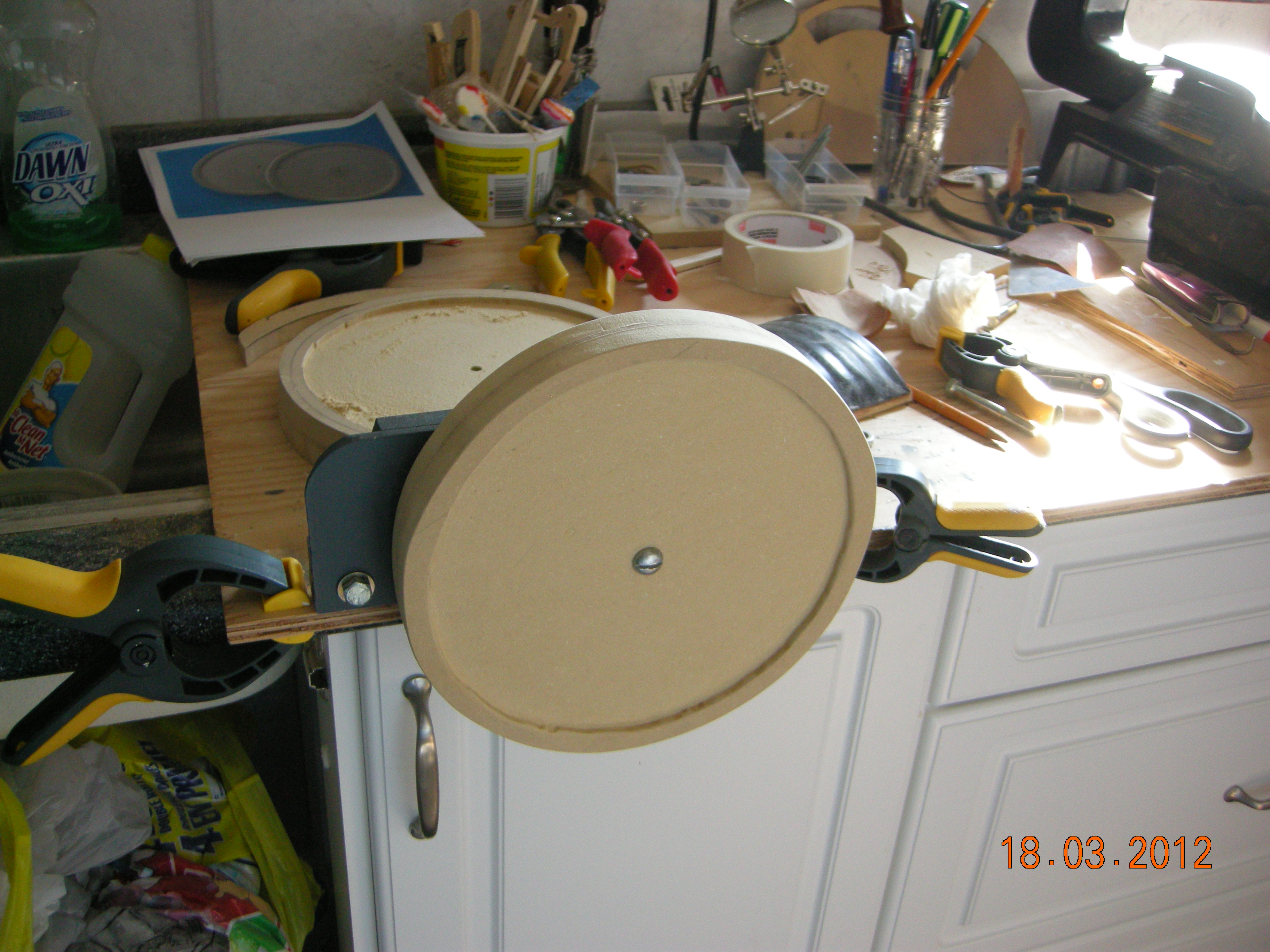
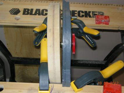
Testing the axis and sanding
|
Center area has been routed out leaving an outside edge
| 
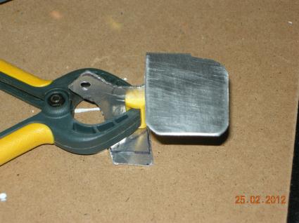
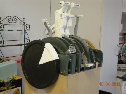
The white triangle I have determined to be 90mm
|
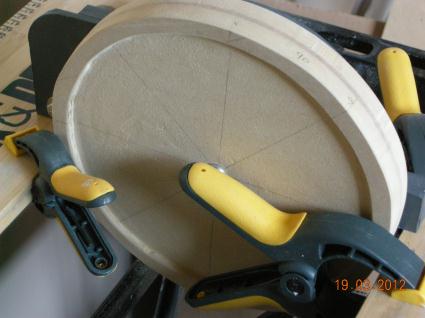
Determining the white trianglular area of the trim wheel.
| 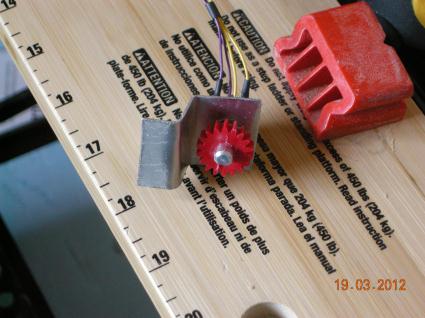
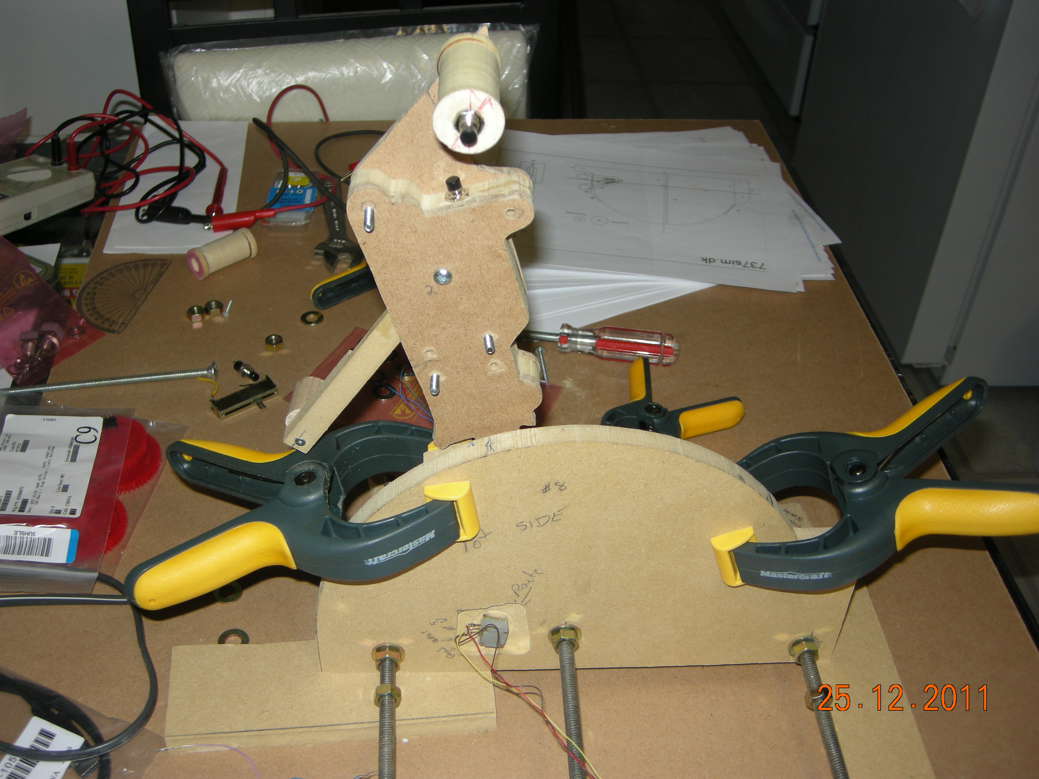
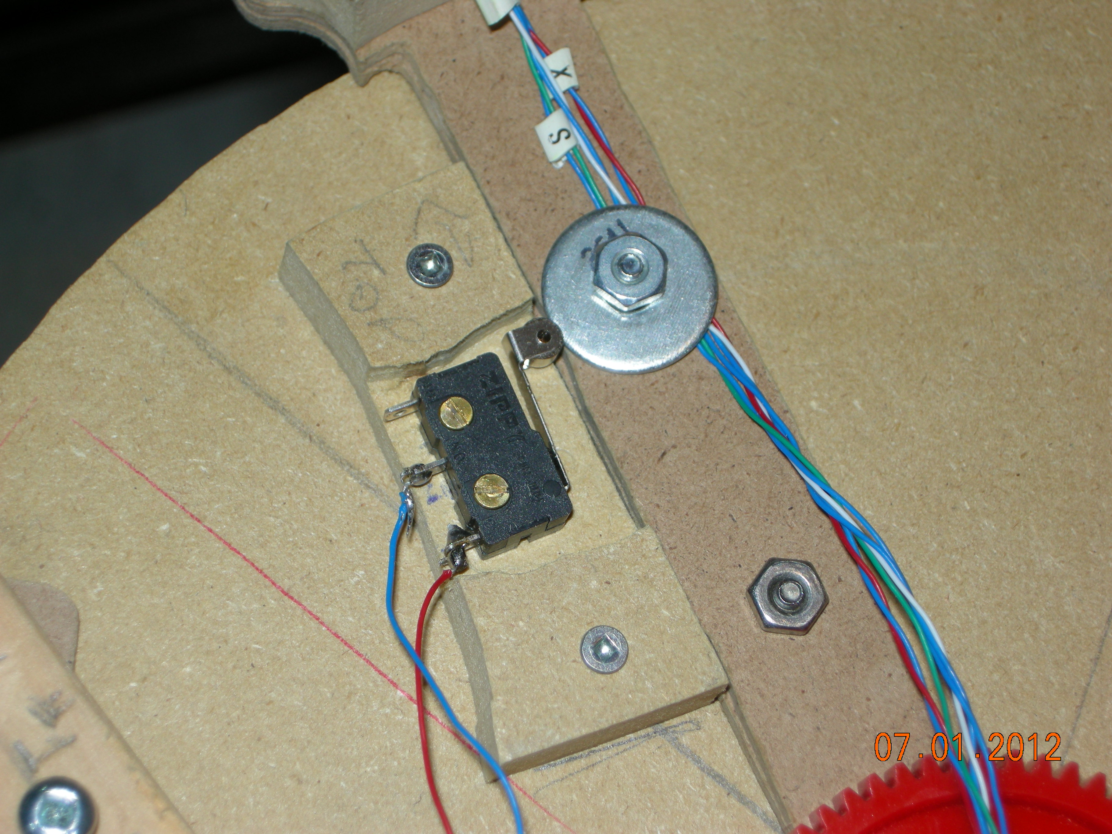
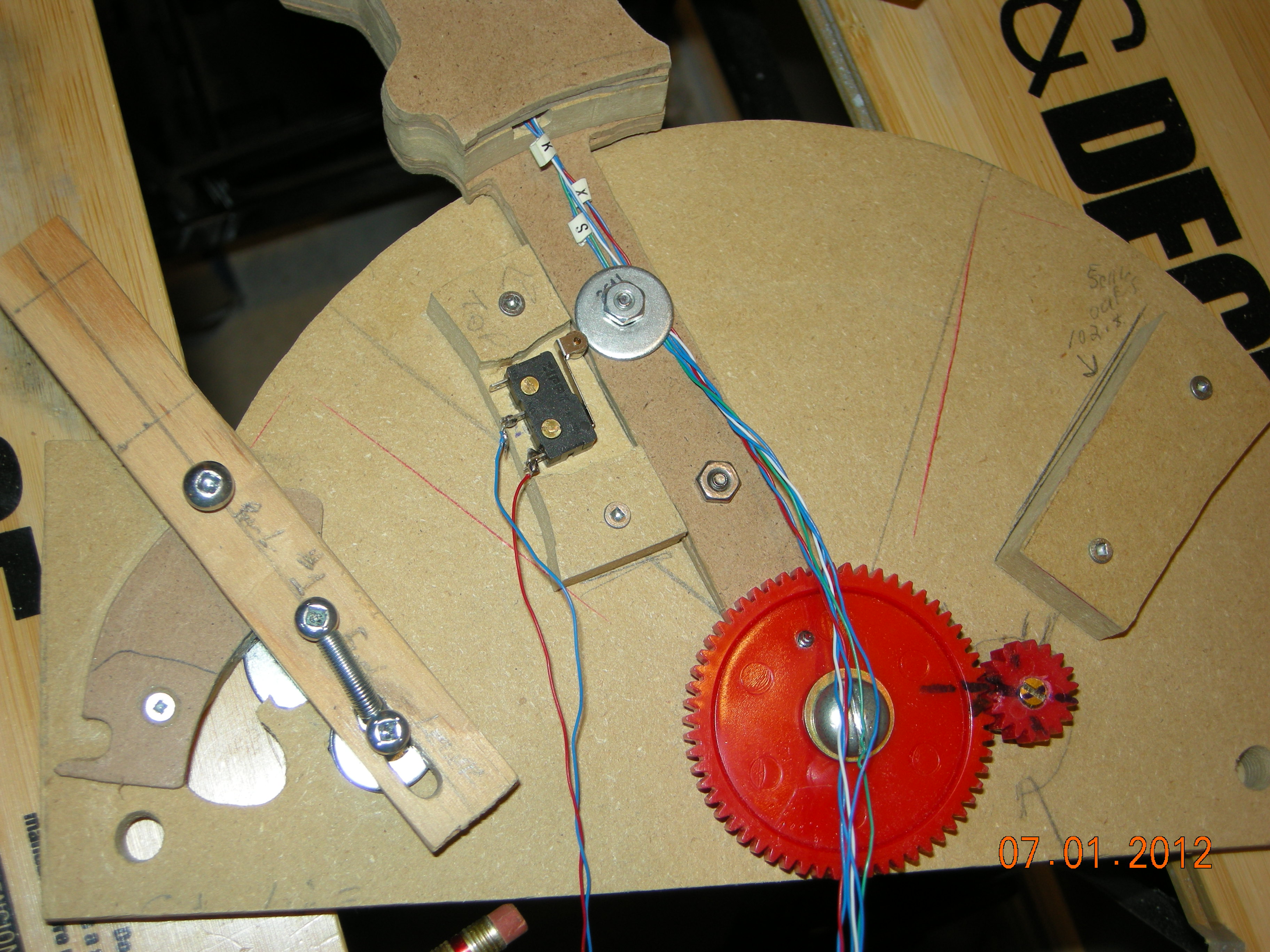
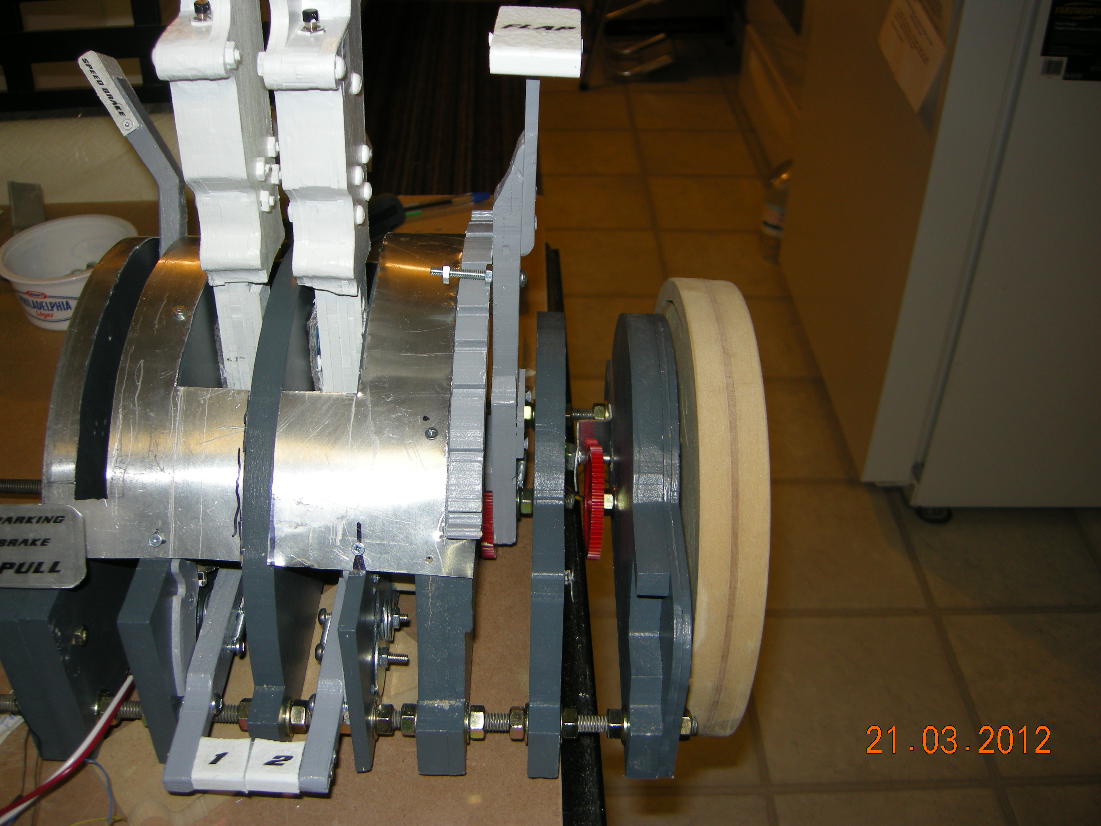
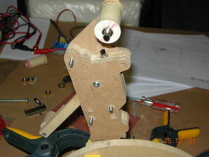
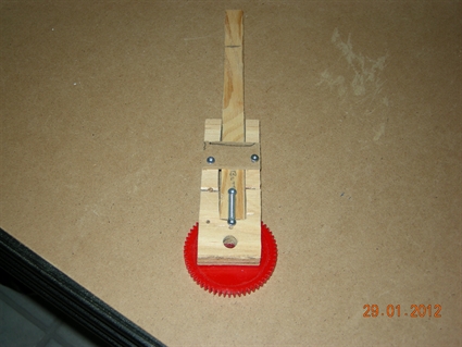
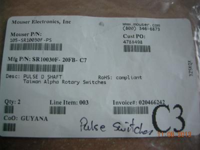
Making the mount for the pulse switch with 18 tooth gear attached.
|
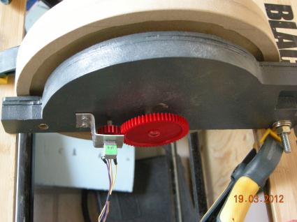
Gears and pulse switch mounted. I estimate with this ratio, one turn of the trim wheel will equal 4 turns of the pulse switch which will equate to one graduation mark on the trim scale.(fingers crossed)
| 
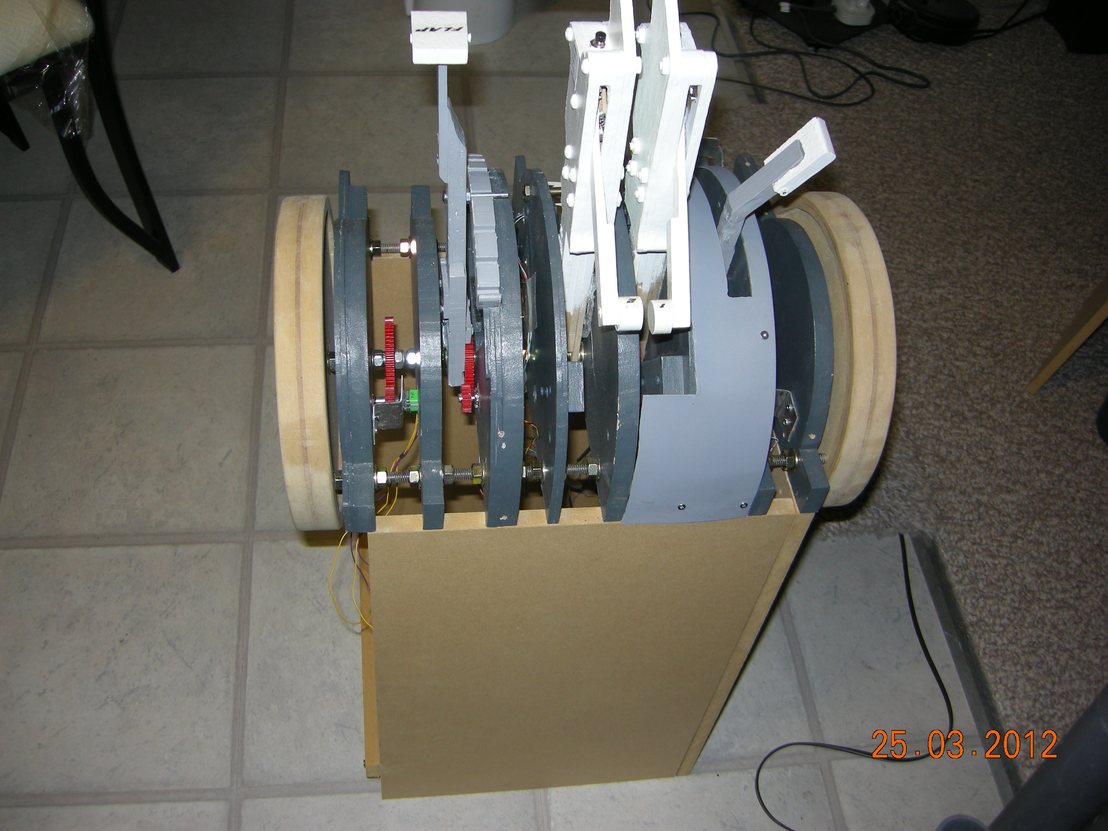
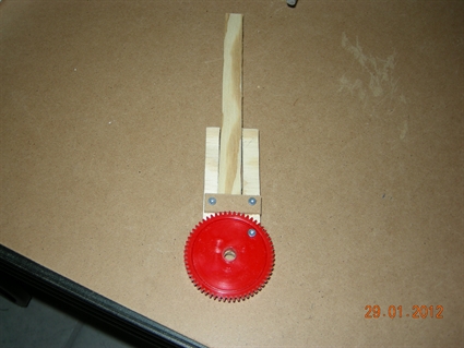
Front view of the trim setup FO side. I later changed the design, went to a longer bolt and held the gear inplace with a lock nut due to high resistance on the rotary switch.
|
Sizing up the FO trim wheel. Roughing in aluminum
| 
Approximatly how FO trim wheel will look
|

Aluminum covers partly mounted.
| 
Pulse Switch and gears in place. I decided to hold the large gear in place with locking nuts as there is a fair bit of resistance on the pulse switch.
|
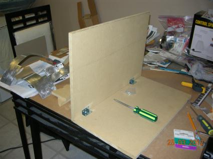
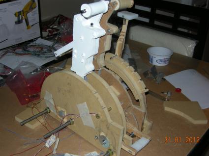
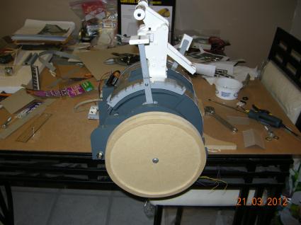
Building the throttle foot. 275mm X 12 1/2 inches X 18 inches high.
| 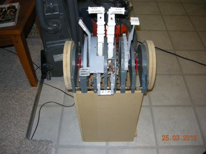
Sits nicely on it's foot. Made of 12mm MDF
|
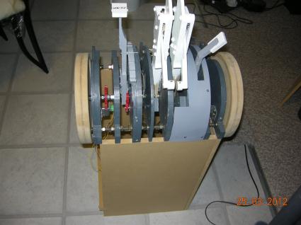
Left one side off for now to allow for access to wiring
| 
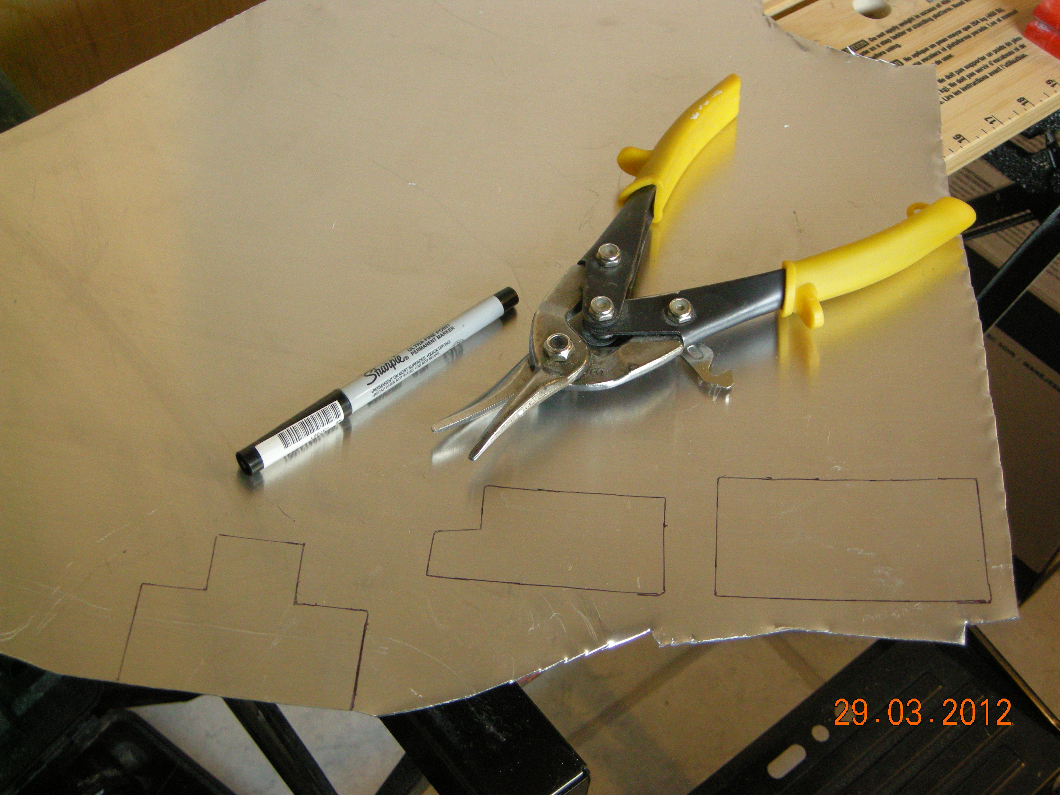
Roughing in the aluminum covers. All cut and shaped by hand, so first appearances will look rough.
|
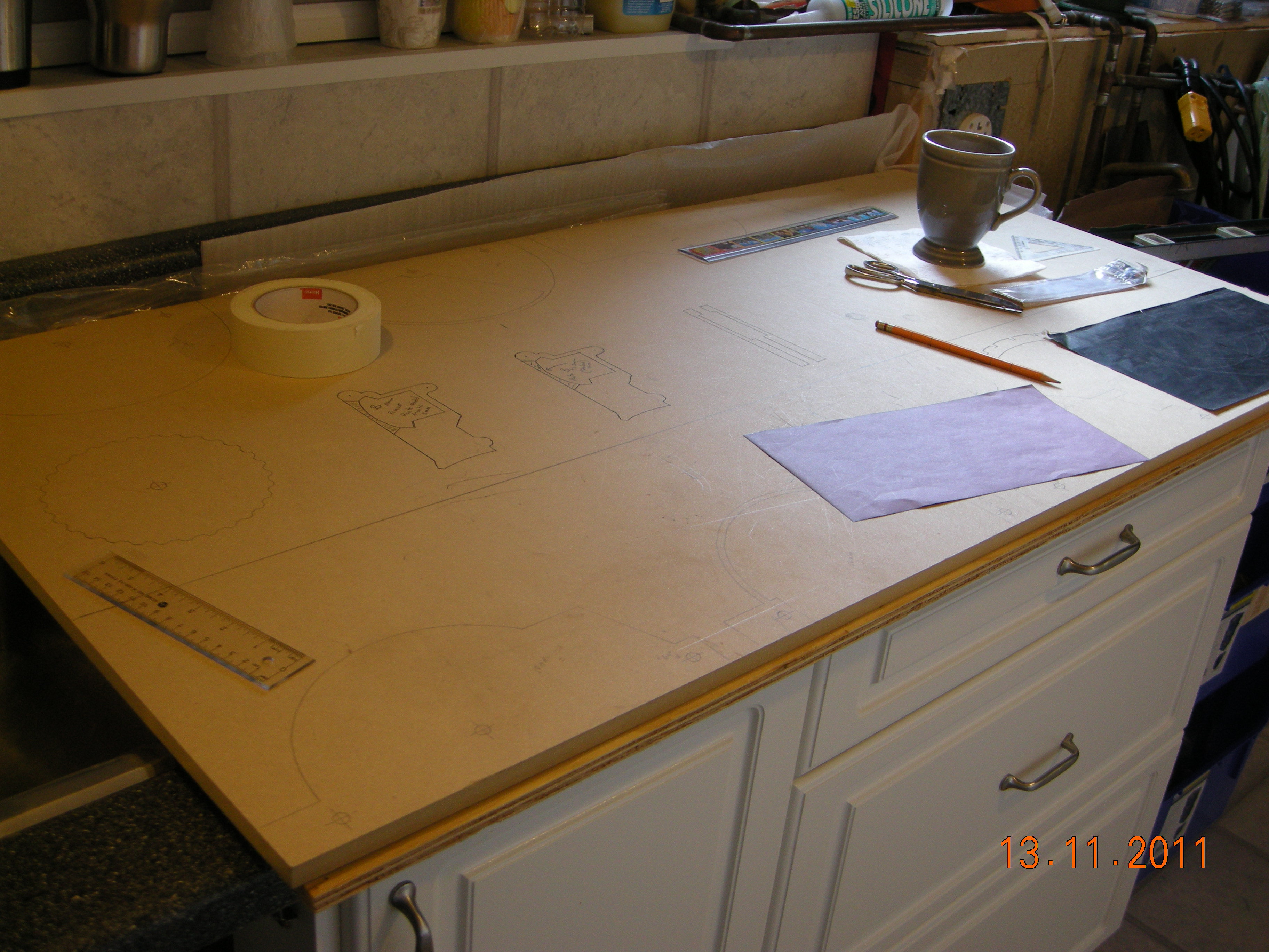
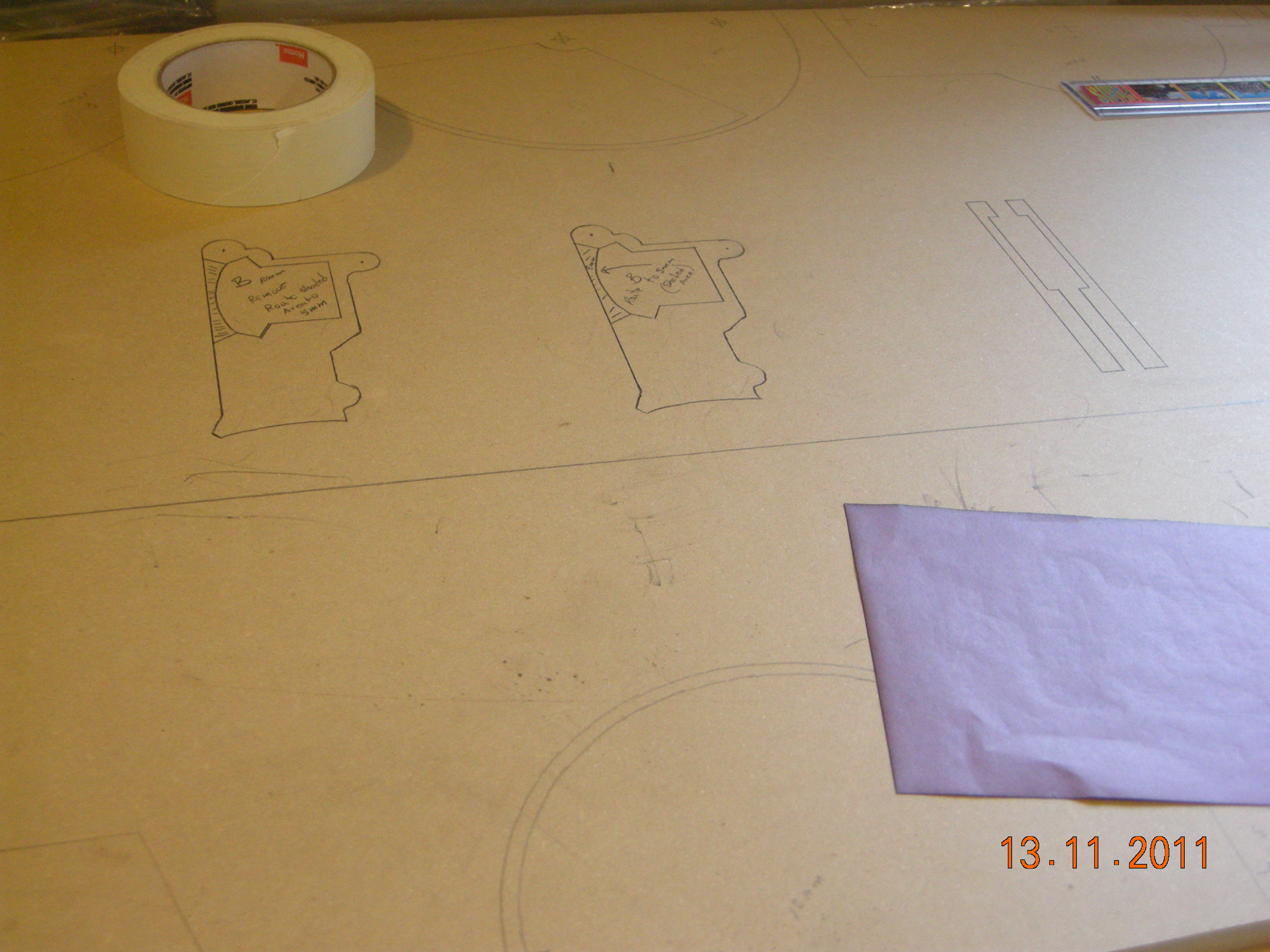
drawing out the parts for cutting
| 
Placing and shaping
|

priming with automotive grey
| 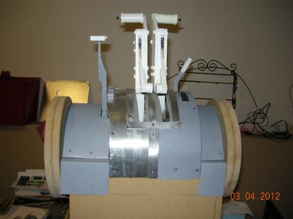
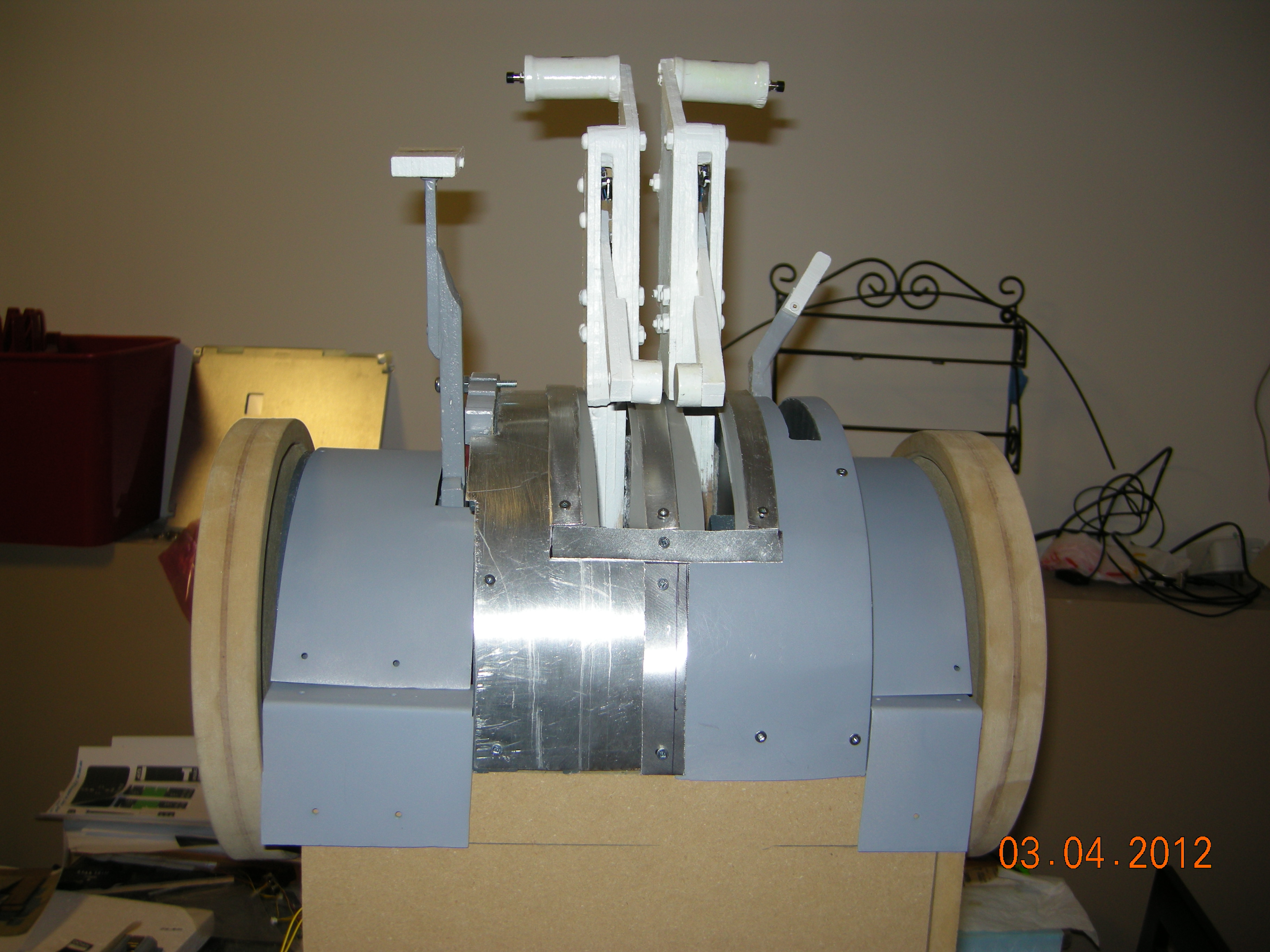
back view
|
Painting trim wheels Black Cat Black and Kitchen and Bath white
| 
Prepping for 9 volt, Bodnar card and graduation plates and dust covers.
|
Installing graduation plates and dust covers
| 
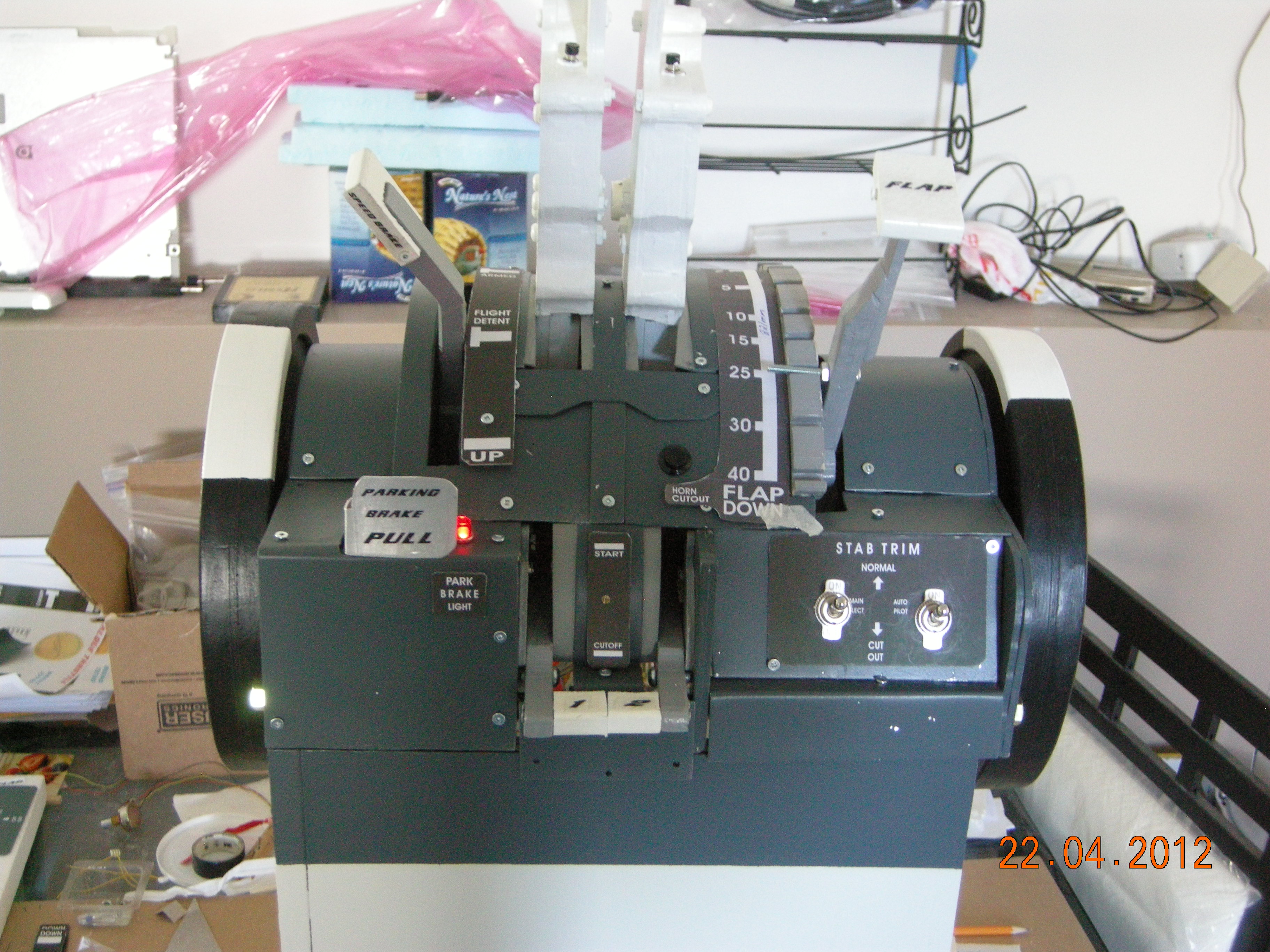
Brake light working, toggles installed. Going to redo the toggle plate
|

Back painted with RAL7011
| 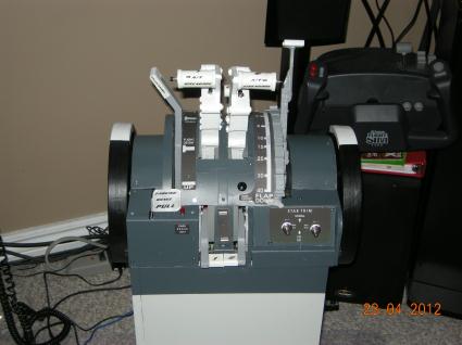
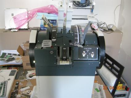
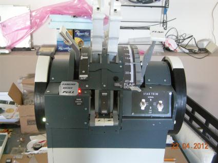
Front painted with RAL7011, pedestal painted with RAL 9002
|
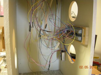
A peek at the internals
| 
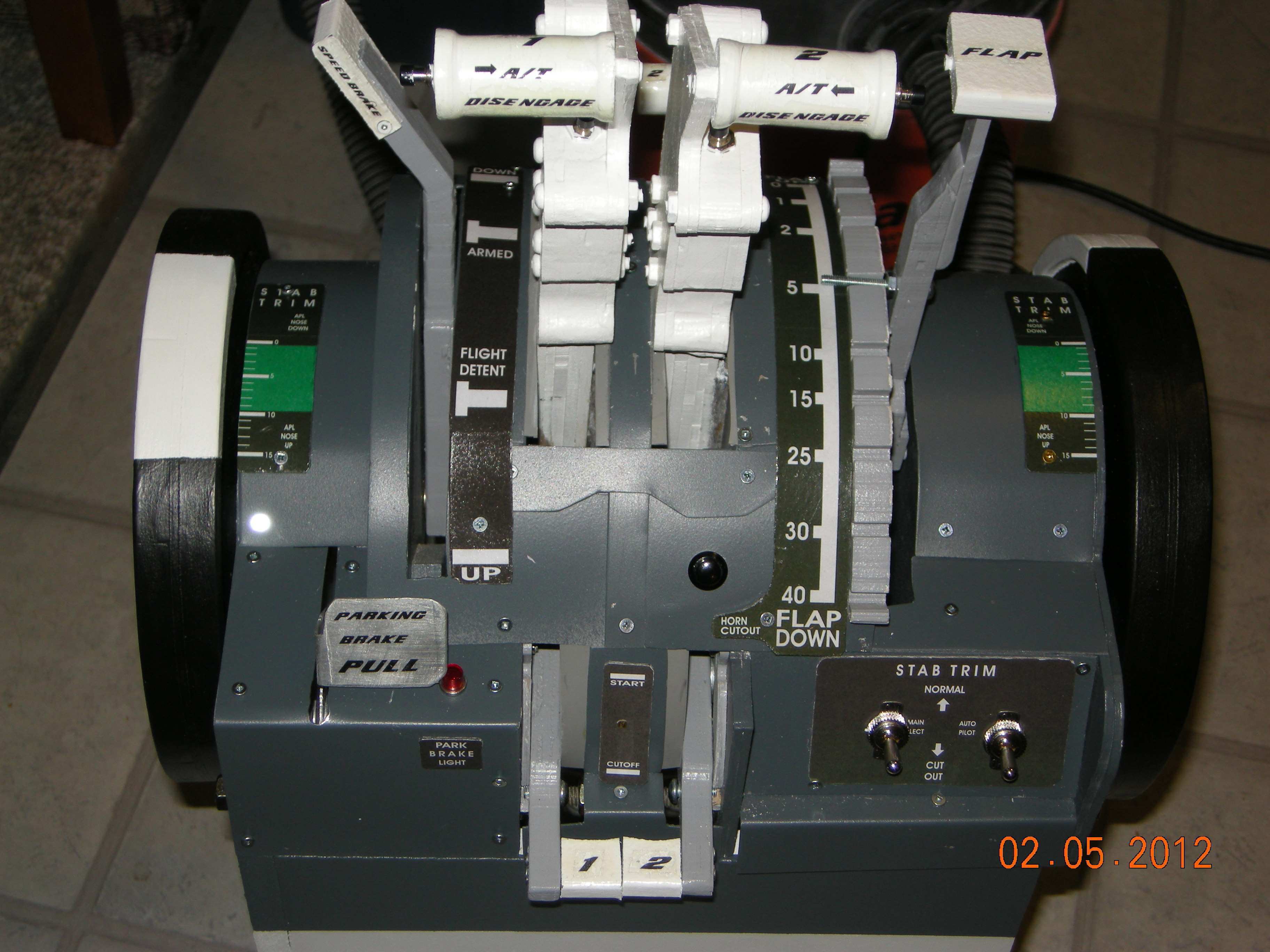
RAL7011 without camera flash
|
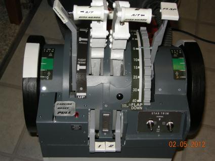
Pretty much complete, I am happy with the results. Graduation plates in place. RAL7011 with camera flash
|
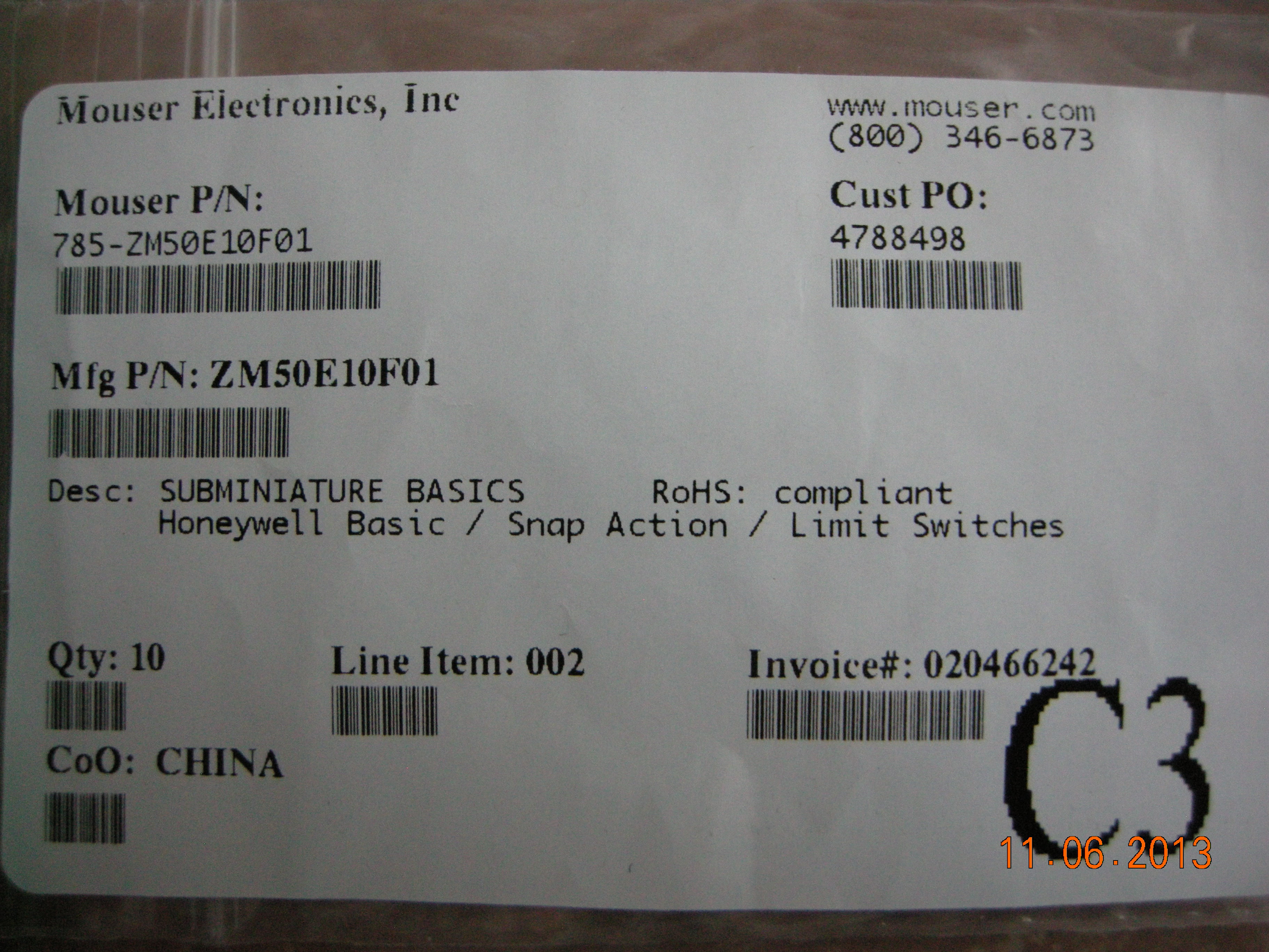
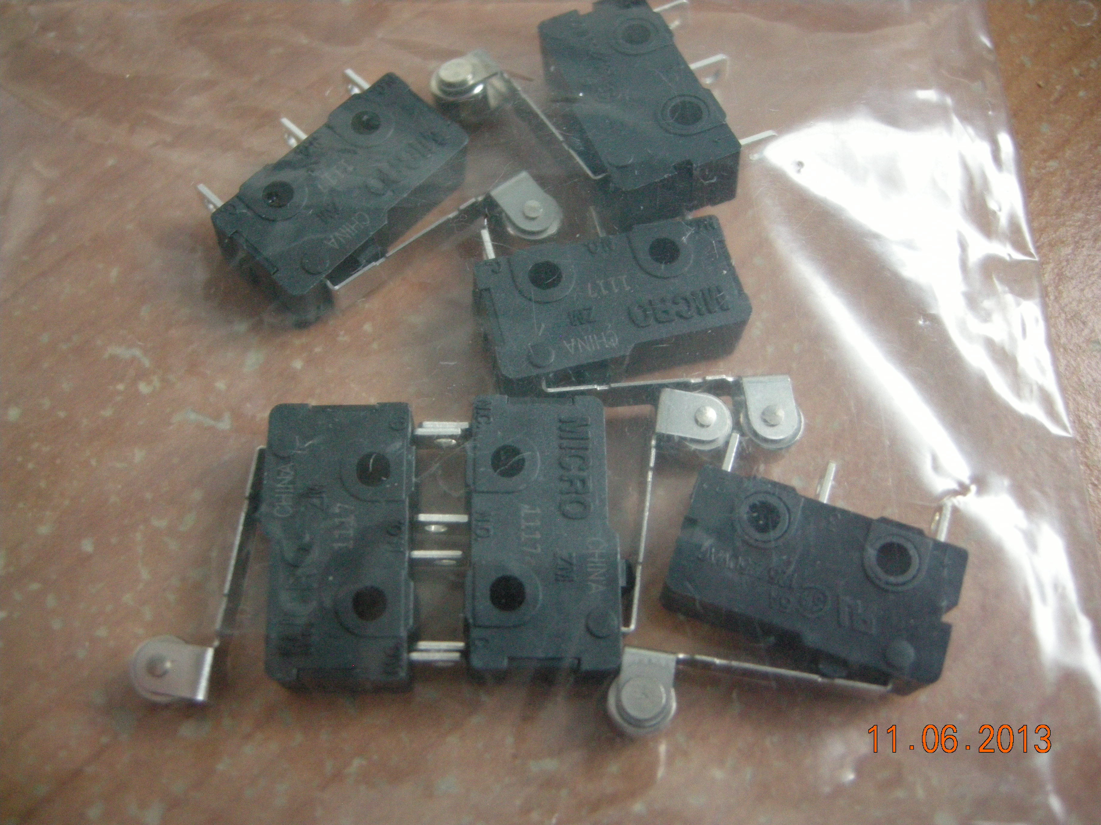
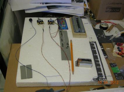
Sub micro switches -->
| 
I used 6 of these
|
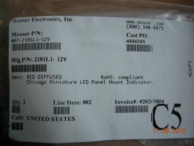
Brake light LED --->
| 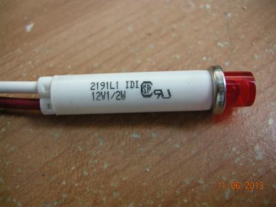
One required
|
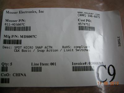
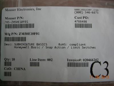
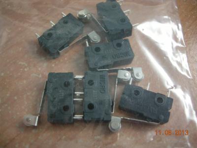
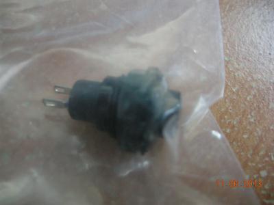
Micro switches -->
| 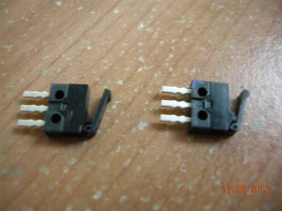
2 Required - 1 per thrust reverse lever
|
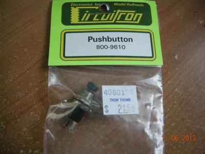
Pushbutton I used 4 - 2 for ATGA and 2 for AT Dissconnect
| 
2 Required - 1 per trim wheel
|
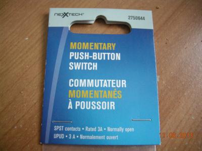
Large black Push button
| 
1 Required - Horn Cut Out
|